Creating a Futuristic Concept Scene: Speed Designing with Photoshop and Blender

Last night, I created a set of simple concept images in roughly 4 hours of on-and-off work. My goal was to quickly develop a partial continuity between two images, establishing a sort of implied workflow utilization. In other words, I wanted to first create a hand drawn digital image of the concept using a pressure sensitive pen tablet. Then, using this drawing as a guide, I wanted to speed model and texture a 3D environment inspired by the drawing, thereby establishing a workflow continuity commonly seen in the industry: from hand drawn concept image to rendered concept image.

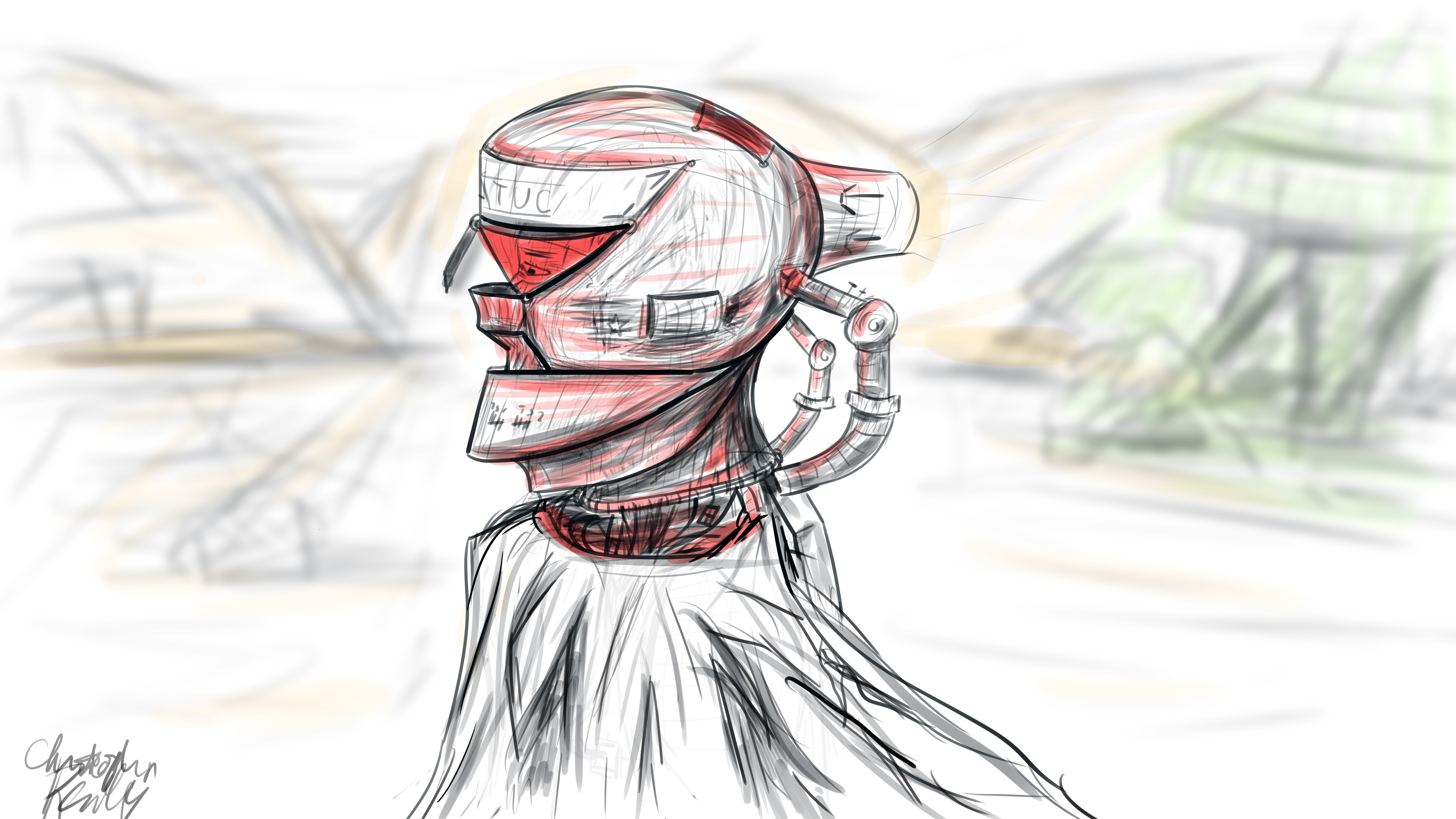
I began in Photoshop, where I set up a 16*9 inch 500 ppi resolution document with no guidelines. I set the pen size to roughly 25 pixels for fine control of the design. I decided to go for a neofuturistic, bleak image of an astronaut of some sort traversing a somewhat barren area. I wanted to combine elements of the past into the image by featuring a draped cloth, which would be covering the lower half of the figure’s visible physique. I began to draw with smoothing at around 50%. I first did a complete sketch of the man’s face from the inner muscle groups outward, even though most of this would later be covered by other elements, such as his helmet. I even included facial hair. The man’s thin face and the shape of his jaw helped dictate where the different elements of the helmet would go, and what shape they would take.

The first defining strokes I made staked out the area that would later make up the visor part of the helmet. I defined the opening that the man would be looking out of, as well as the collar piece and other essential components of the structure. Once I had pieced the entire structure together, I began shading the image according to the geometric contours using various pen widths and shapes until I was satisfied. I blocked out elements of the man’s bare face using white shapes with various opacities to define the surface of the helmet.

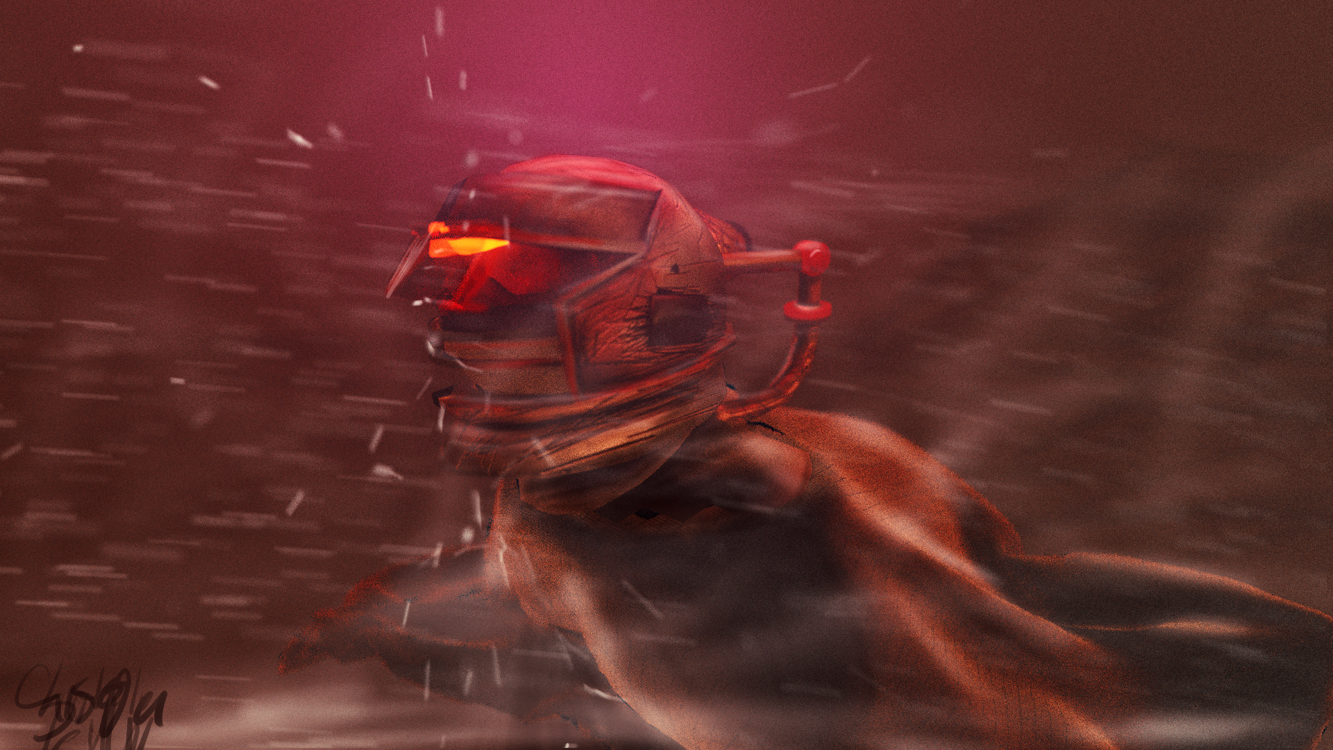
To go from 2D to 3D, I first sculpted the man’s bare face using the sculpting tools in Blender. I then began forming the geometric segments of the helmet around the face according to their required positions. I frequently adjusted the design and shape of the pieces on the fly as I went. When I was ready, I used Blender’s texture paint features to literally draw on color and damage marks, and applied these image textures to the model pieces in the node compositor. I used glossy shaders for the most part, and reused the hand drawn textures as displacement maps to give depth to the material.

To achieve the cloth look, I created a subdivided plane with a hole in the middle around the figure. I “pinned” the vertices at the center so that they would not move, and then ran a cloth simulation using wind and turbulence forces to achieve a billowing cloak model. I textured this using a combination of an opaque velvet shader and a transparent shader in a mix shader, with the factor set to a stretched brick texture. This gave me long strands of “cloth”, which looked like a woven burlap material up close.

I then ran a particle system with wind and a collision object to simulate snow, and rendered this separately. I pulled everything into Photoshop, applied a lookup table, touched up highlights and shadows using the brush tool, and composited dust and smoke into the shot, and rendered it out. The resulting image is comparable to the original sketch, albeit vastly different in proportion.

This exercise has given me some insight as to how concepts tend to change from conception to execution, and how one might go about adapting reference images for use in 3D environments. To see more of my work, go to www.newflightdigital.com. Feel free to reach out to me at contact@newflightdigital.com.

Home Automation Scripting with the Raspberry Pi: Update #1

Over the past year, I have experimented with different methods of home automation, from scripts that automatically render my projects for me, to light control. In this time, I have been using an old E-machines desktop computer with a failing hard disk and limited RAM. Well, this holiday season, the thing finally gave out on me, but luckily I had a spare Raspberry Pi to fill this void. I transferred the necessary scripts that I had written, as well as the necessary programs that I had found online and compiled. The current system has my Pi mounted to a wall on one end of my room with a status monitor, connected to a very long USB cable which snakes around the perimeter of my room to the opposite wall. There, the USB cable is connected to a USB hub which connects to a USB-DMX dongle (to control RGB lights), and a USB relay module to control a tower light and buzzer set for special alert cases. The whole thing is controlled by a script that checks a Google Firebase database every 5 seconds for changes. I have created an Android app using MIT App Inventor which communicates with the same Firebase database, thereby communicating with the Raspberry Pi over the internet. With this setup, I can change the color of my room lights, tell the Raspberry Pi to say a specific phrase, and more. To date, my home automation system is equipped with the following abilities:

  • A briefing program, which uses Linux’s “espeak” text to speech terminal program to address me and give me updates on the status of various processes. For this program, the script first gathers various statistics by loading up various web pages, saving them into text documents, and parsing them. For example, the briefing program provides the weather, temperature, the number of followers on each of my social media accounts, as well as more personalized data such as the number of files rendered over night.
  • A continuous social media checker, which alerts me when I gain or loose a follower on Instagram by telling me verbally and by turning the LEDs in my room either green or red.
  • Full LED lighting control via a USB-DMX interface, and a strip of RGB LEDs connected to a DMX decoder.
  • A facial recognition program that uses a webcam connected to the Pi, complete with a full login and logout system, which can recognize a person entering the room and identify them, setting the room state to their preference.
  • A custom phrase repeater, which gets its phrase from the Android app.
  • A custom alarm clock which will read input from my app, setting an alarm for the appropriate time and waking up the room occupant at the appropriate time using voice features.
  • And much more!
On the left, the wall mounted black box is the Pi. The screen above it will soon display statistics, current system state information, and security data.

As I mentioned above, the two main complex connections involved with this setup are the USB relay module, and the USB-DMX interface. I managed to find open source command line programs for Linux online to control both the USB relay module and the USB-DMX interface. Just pure luck! Below are images of both interfaces.

A USB cable from the hub connected to the Pi connects to the USB-DMX interface, which plugs into this DMX decoder, which then receives power from the left and splits the signal into the appropriate RGB channels for the lights.
A USB cable from the hub connects to this relay module, which receives power from the left. According to the signals received from the Pi, the relay module will open or close the relays, thereby turning on or off the different components on the tower light.
This is the tower light, which includes a buzzer and 3 lights.

Above, you can see a screenshot from the light controller portion of my app, and some of the lighting options.

This has been a very, very brief overview of the system. Parts of it, such as the facial recognition system and the relay control, took many days to set up and get working properly. If you would like to know more, leave a comment requesting a future blog topic!