Home Automation Scripting with the Raspberry Pi: Update #1

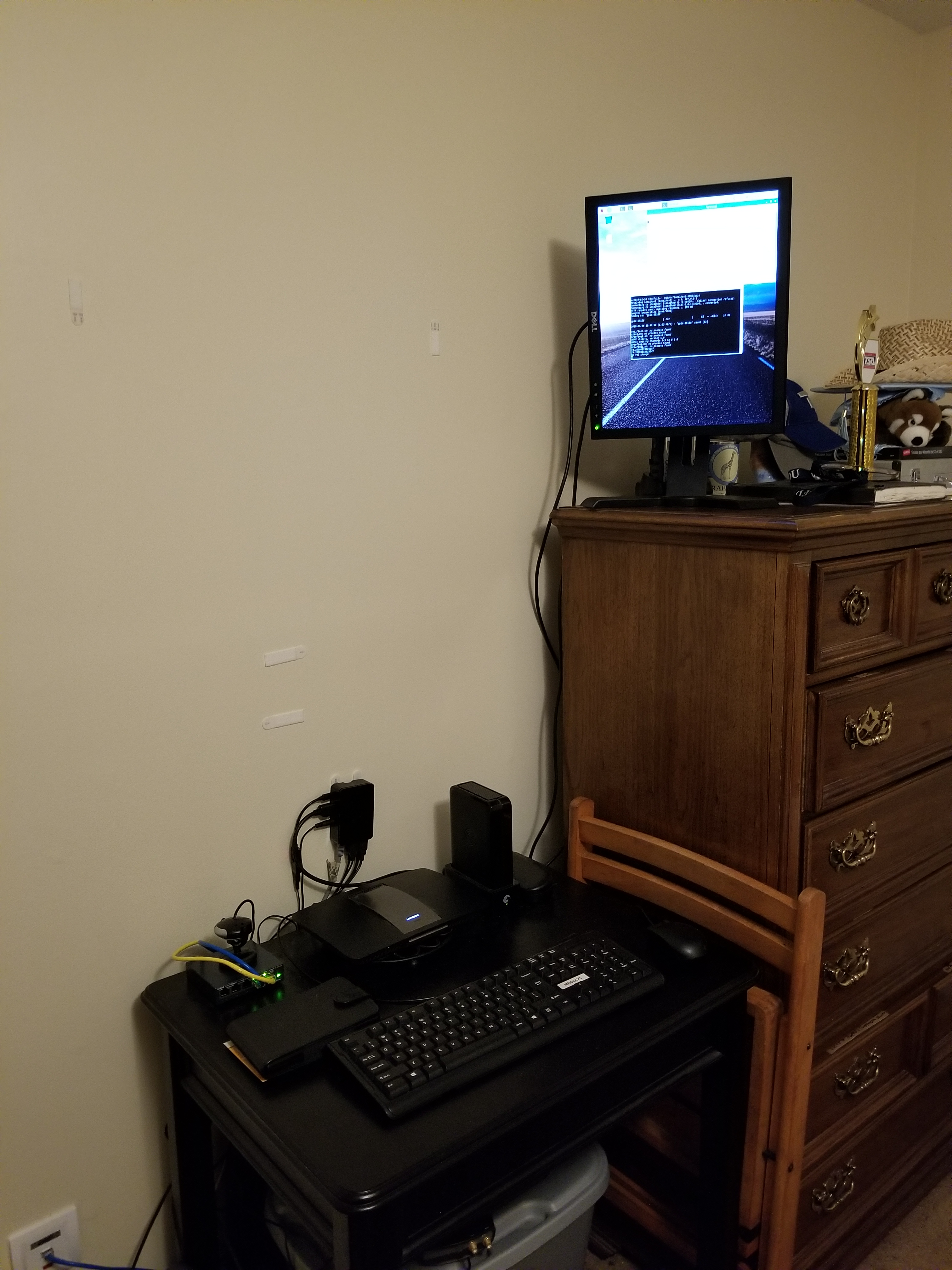
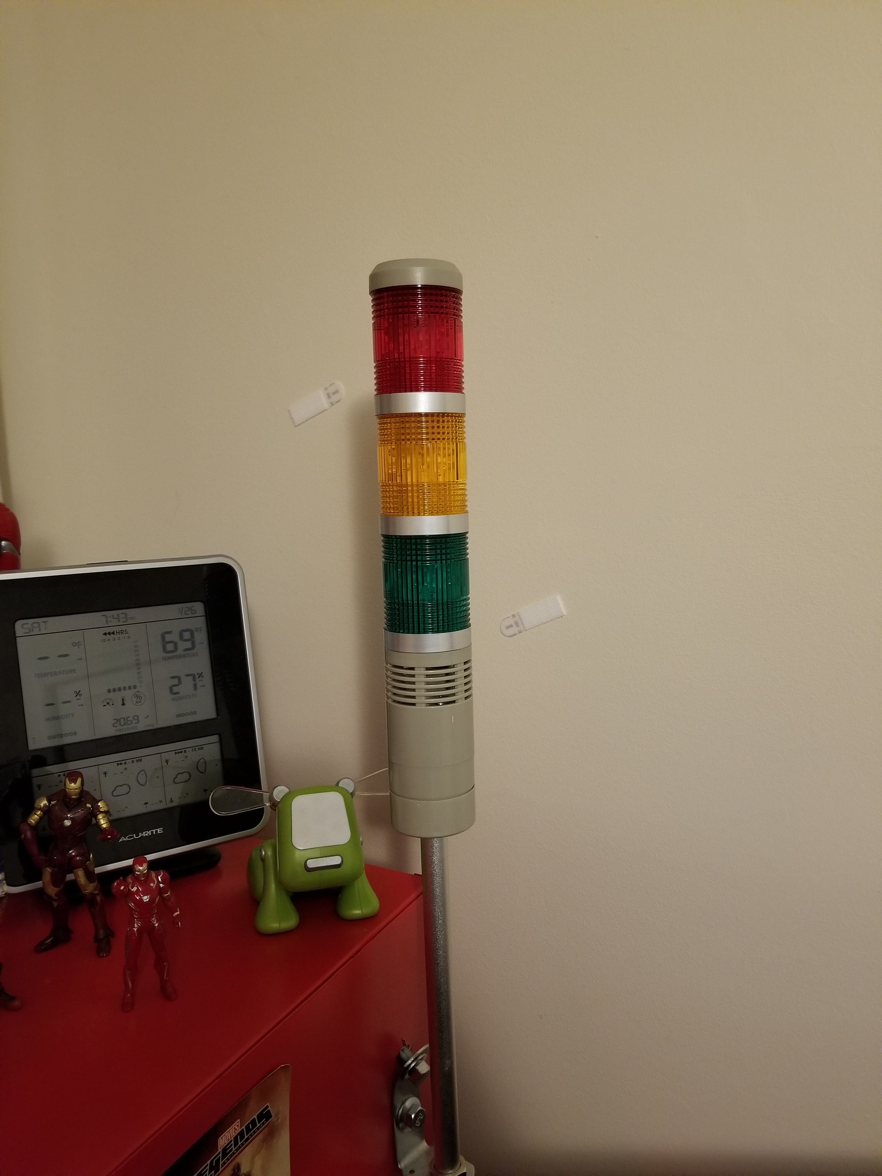
Over the past year, I have experimented with different methods of home automation, from scripts that automatically render my projects for me, to light control. In this time, I have been using an old E-machines desktop computer with a failing hard disk and limited RAM. Well, this holiday season, the thing finally gave out on me, but luckily I had a spare Raspberry Pi to fill this void. I transferred the necessary scripts that I had written, as well as the necessary programs that I had found online and compiled. The current system has my Pi mounted to a wall on one end of my room with a status monitor, connected to a very long USB cable which snakes around the perimeter of my room to the opposite wall. There, the USB cable is connected to a USB hub which connects to a USB-DMX dongle (to control RGB lights), and a USB relay module to control a tower light and buzzer set for special alert cases. The whole thing is controlled by a script that checks a Google Firebase database every 5 seconds for changes. I have created an Android app using MIT App Inventor which communicates with the same Firebase database, thereby communicating with the Raspberry Pi over the internet. With this setup, I can change the color of my room lights, tell the Raspberry Pi to say a specific phrase, and more. To date, my home automation system is equipped with the following abilities:

  • A briefing program, which uses Linux’s “espeak” text to speech terminal program to address me and give me updates on the status of various processes. For this program, the script first gathers various statistics by loading up various web pages, saving them into text documents, and parsing them. For example, the briefing program provides the weather, temperature, the number of followers on each of my social media accounts, as well as more personalized data such as the number of files rendered over night.
  • A continuous social media checker, which alerts me when I gain or loose a follower on Instagram by telling me verbally and by turning the LEDs in my room either green or red.
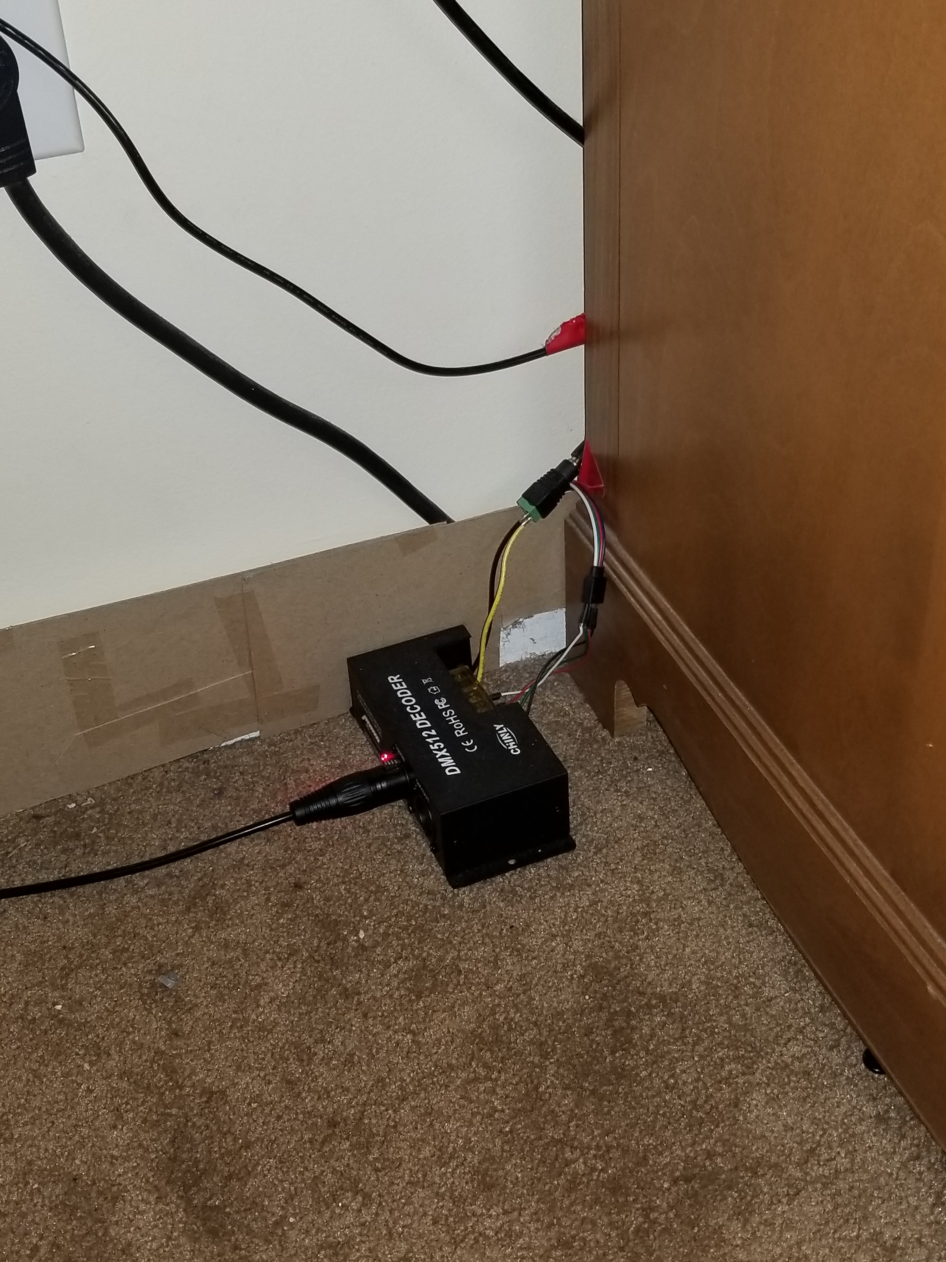
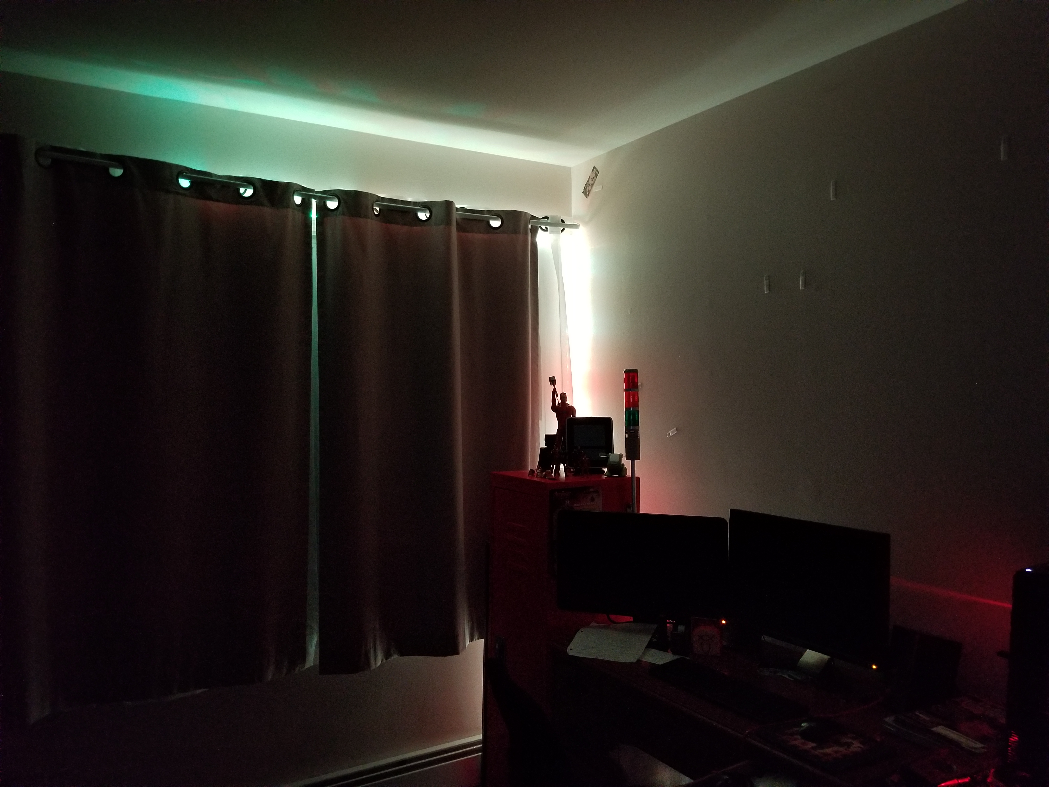
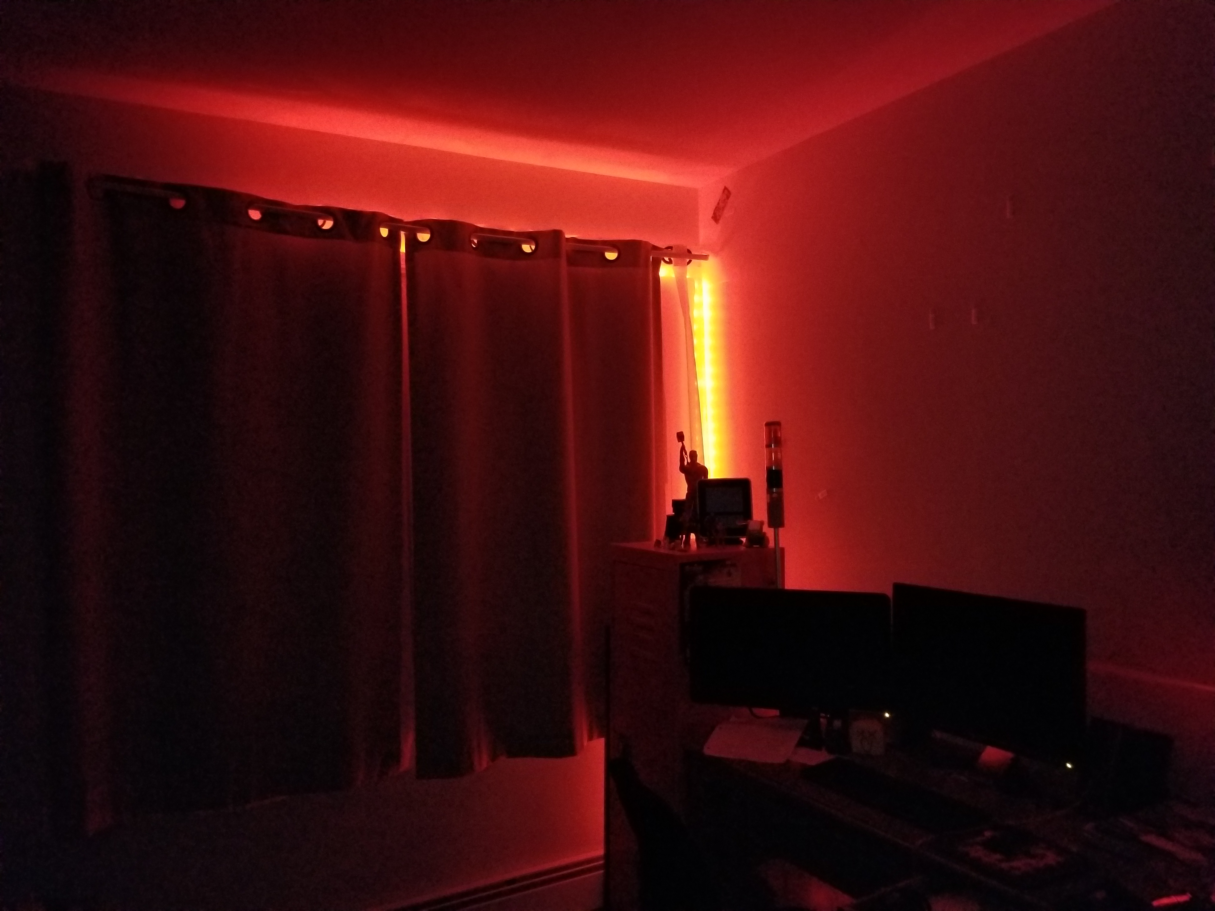
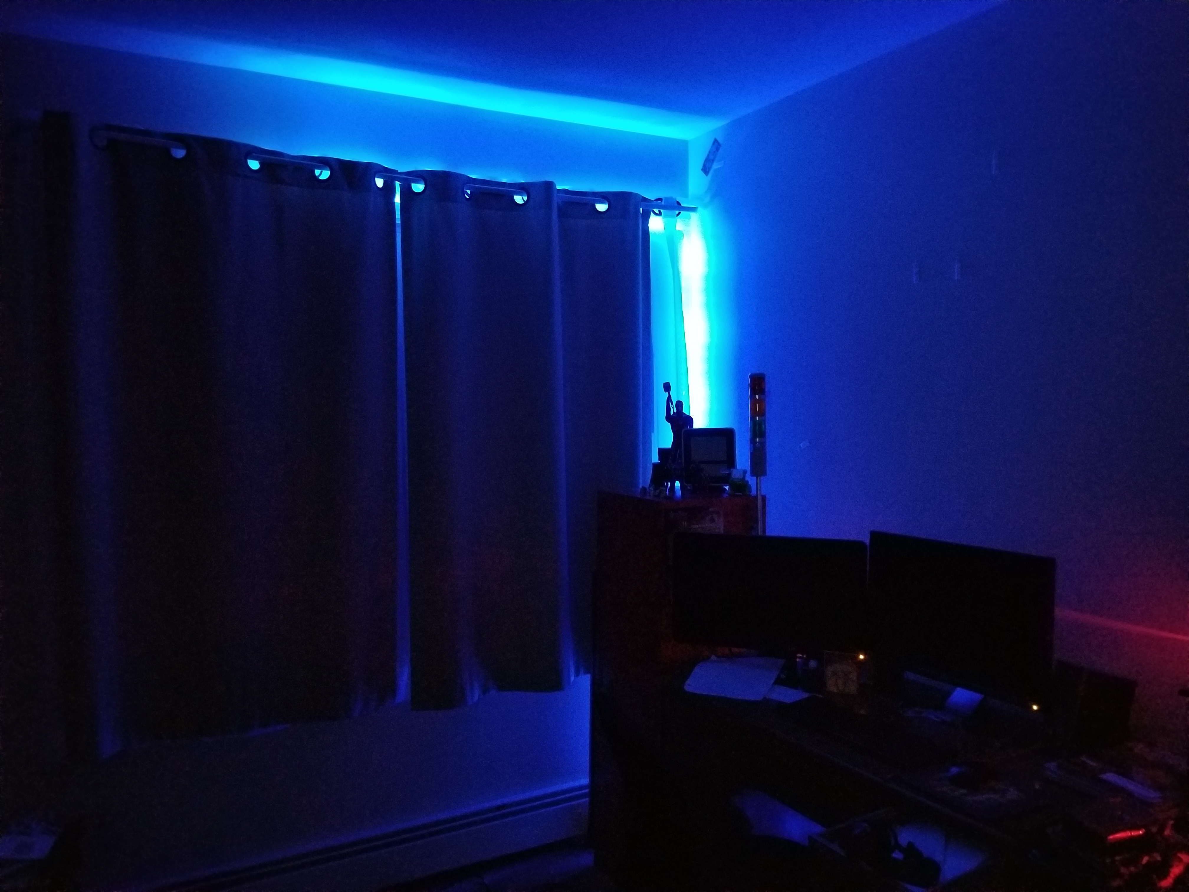
  • Full LED lighting control via a USB-DMX interface, and a strip of RGB LEDs connected to a DMX decoder.
  • A facial recognition program that uses a webcam connected to the Pi, complete with a full login and logout system, which can recognize a person entering the room and identify them, setting the room state to their preference.
  • A custom phrase repeater, which gets its phrase from the Android app.
  • A custom alarm clock which will read input from my app, setting an alarm for the appropriate time and waking up the room occupant at the appropriate time using voice features.
  • And much more!
On the left, the wall mounted black box is the Pi. The screen above it will soon display statistics, current system state information, and security data.

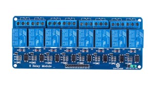
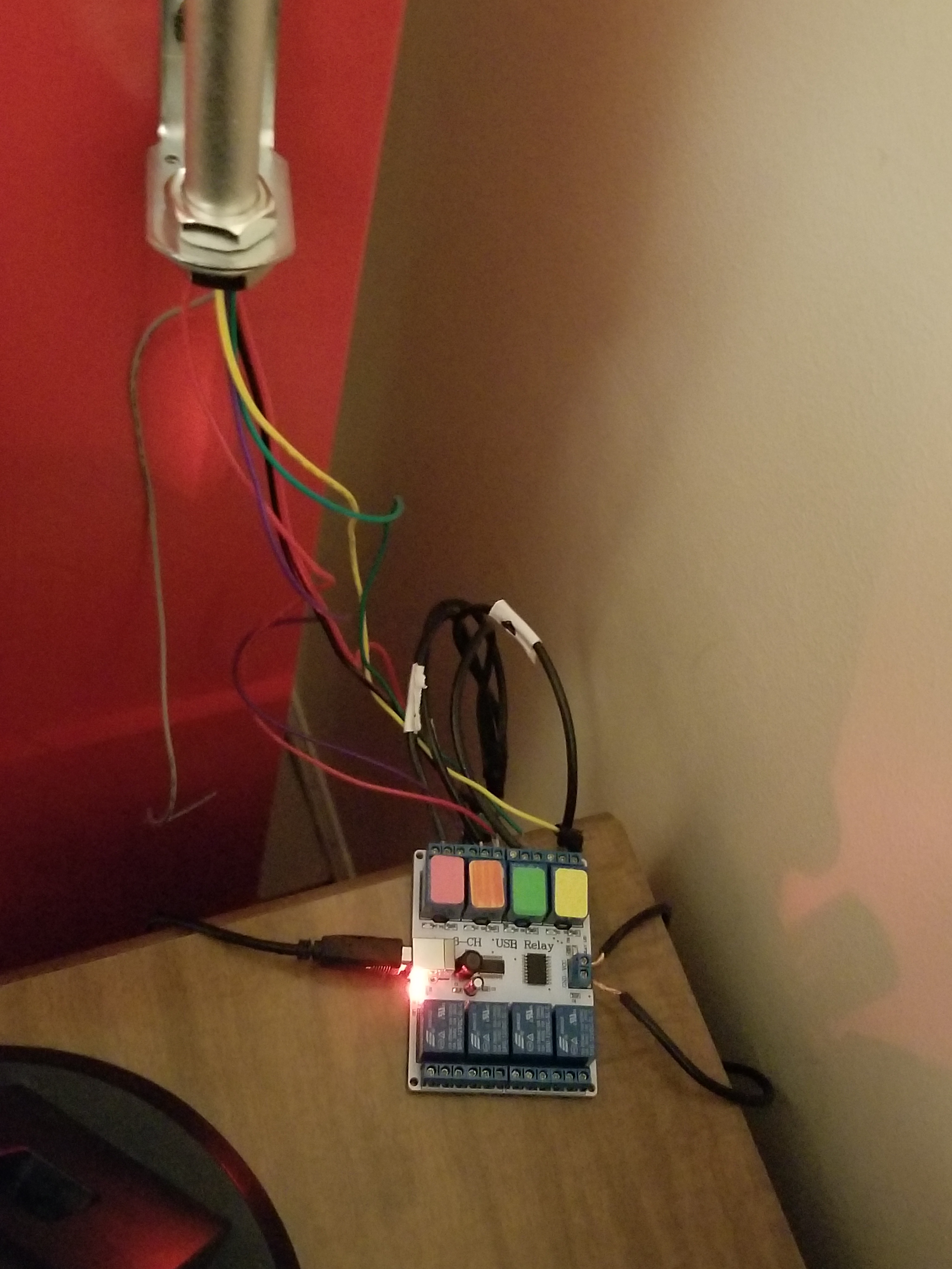
As I mentioned above, the two main complex connections involved with this setup are the USB relay module, and the USB-DMX interface. I managed to find open source command line programs for Linux online to control both the USB relay module and the USB-DMX interface. Just pure luck! Below are images of both interfaces.

A USB cable from the hub connected to the Pi connects to the USB-DMX interface, which plugs into this DMX decoder, which then receives power from the left and splits the signal into the appropriate RGB channels for the lights.
A USB cable from the hub connects to this relay module, which receives power from the left. According to the signals received from the Pi, the relay module will open or close the relays, thereby turning on or off the different components on the tower light.
This is the tower light, which includes a buzzer and 3 lights.

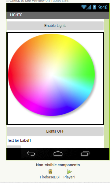
Above, you can see a screenshot from the light controller portion of my app, and some of the lighting options.

This has been a very, very brief overview of the system. Parts of it, such as the facial recognition system and the relay control, took many days to set up and get working properly. If you would like to know more, leave a comment requesting a future blog topic!

Creating an Internet Controlled Rover with an Old Kids’ Car and a Raspberry Pi

I would like to talk about an extended project I did this past summer, which forced me to learn bash and batch programming, expanding my abilities for the future. The original idea was to take this old remote control car I had and make it controllable over the internet… from anywhere. I called up my friend, Thomas Nast, for help with this one.

The plan was simple: have a power source to power the Raspberry Pi, and a power source for the car. The Raspberry Pi’s GPIO pins would be connected to a relay module (basically a set of electromagnetic switches that the Pi can turn on and off). When the Pi applies 5v of electricity to a pin, the electromagnet in the switch electrifies, closing the switch. When the power shuts off, the switch flicks open with the help of a spring. In this way, you can control the flow and direction of electricity. There are 8 relays in a relay module in total. We created a circuit that could, if properly programmed, run the car backward, forward, left and right. It just depended on which switches were opened and closed.

8-ch-relay-module_01
An 8 Port Relay Module

As for the Pi’s programming, the first step was to get it to connect to our VPN upon startup. We simply ran OpenVPN on startup with a configuration file (which sounds easier than it actually is… finding the right mechanism to do so is challenging on Raspbian). After that, I wrote batch scripts that would send UDP commands from my laptop with ASCII strings, one for each direction. Then, I mapped an XBox Controller to each script operation, so that upon pressing, say “left” on the D Pad, a specific keystroke would be input to the batch script, and the “left” part of the script would run, thereby sending a UDP command for “left” to the Pi’s IP address. Now my laptop could send UDP commands to an IP Address and Port of my choosing, over a VPN, all with an XBox controller (the laptop had to be connected to the VPN, of course).

I then wrote a script for the PI to listen for UDP packets on a specific port and, upon capturing one, save the packet into a text document and search for specific strings in the document. If the ASCII text string for any given command was found, it would run the appropriate bash script which would apply voltage to the appropriate GPIO pins, thereby opening the relays on the relay module, and thereby completing the correct circuit, moving the motors. If current came from one direction in the circuit, the motors would run in one direction, and vice versa. Therefore, the circuitry became quite advanced quite quickly to allow us to send electricity in either direction (to allow for forward and backward movement).

My first prototype ran on two 5V portable phone chargers: one for the Pi, and one for the two motors. The tests were successful, although the small 5v motors barely carried the two massive battery banks:

The real prototype, however, came when we spotted an old kid’s car on the side of the road. You know the type: the kind you drive around a spacious backyard. We took it home, salvaging the back two wheels and the two 12v motors inside. We stripped it down until we found the contacts for the two motors. We then purchased a third wheel to create a three-wheeled structure, and purchased a hefty 12v battery to power it. Then, my friend Thomas designed and 3D printed a strong bracket to connect the back wheel assembly to the wheel bracket.

Screenshot_20180808-100920_Snapchat
The three-wheeled structure without battery, relays or Raspberry Pi

Next, I rewrote the code so that turning “left” simply meant running the right wheel forward while disabling the left wheel, and vice versa for turning “right” (previously, we had had a whole separate motor- the front wheel motor- to control “left” and “right”, and we had had to send current in direction A or B to control the direction that the motor turned the wheels). I also was EXTRA careful not to have the code short the battery at any point, even if only for a moment, since the lead acid battery we are using would probably be damaged. After weeks of adjusting component positioning and other trial and error factors, we ended up burning through two relay modules before we realized we needed flyback diodes to dissipate the current, which was arcing through the relays and welding them shut. We also cracked two of the 3D printed wheel brackets before we decided to make them almost solid plastic.

4igc7
An approximation of the circuit we used to dissipate the current using the diodes (courtesy of Electrical Engineering Stack Exchange)

After ordering our second relay module and a package of flyback diodes, we actually installed the diodes backwards and fried the second module. My friend left for college, and just as things seemed as though we would not be able to complete the project by the end of the summer, the third relay module came in the mail and I threw the circuit together. Featured on the new prototype was a safety switch to break the circuit enclosed in a circuit box with a proper cover, courtesy of my friend, Thomas. Then, there was only one step left to be able to effectively remotely pilot this thing around my backyard over the internet: the device needed to be able to stream video. I added a USB webcam and a command line streaming program to the Pi, and set it to start on startup. I recorded the port it was streaming on, added a high amperage 5v battery bank to power the Pi, and voila! Drone car that is totally controllable over the internet, and that can be viewed over the internet.sulle-1

Resized_20181028_214038_8276
The final prototype, front.

back

The resulting device can, indeed, be controlled via a VPN connection. As long as the Pi has internet access, it can be controlled over the internet (you just have to guess the Pi’s IP address on the VPN to control it… I will fix that later by getting the Pi to report its IP to my laptop). Drawbacks: definitely stability. The three-wheeled design lends itself to flipping over, although I have only seen that when going in reverse (with the single wheel in the lead). The device also likes to veer off track, definitely due to the lack of traction on the wheels. Also, the UDP commands sometimes get dropped, and are very delayed, making controlling the device more like controlling the Mars Curiosity Rover (there is a HUGE delay). Nonetheless, in field tests I was able to pilot the prototype with an XBox controller while viewing the video stream on a laptop.

For more information on this project, leave a comment on this blog post, or reach out to me at contact@newflightdigital.com.