In 2020, company websites are not just about delivering information anymore. As interactivity on the web increases through the use of social media, customers have come to expect that same level of interactivity from the websites they frequent. Think of your website as a micro-experience: instead of simply handing your customers a list of office hours, you’re now engaging them and involving them in an experience they’re more likely to remember the next day.
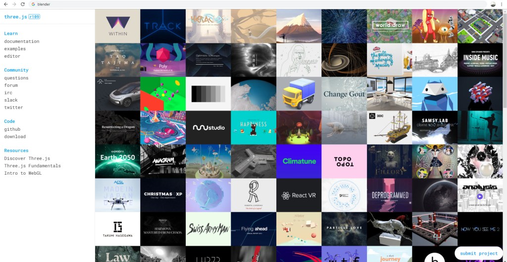
With the advent of WebGL, larger or tech-savvy companies have been quick to take advantage of 3D web graphics. The examples are endless. Here are some of my favorites from this awwwards.com list:
As I described in a previous blog post, I’ve used 3D graphics to bring my website to life and showcase my skills. I want to bring this tool to the people that really need it: small business owners. Sell a hand crafted product? Well, you could always throw a few photos on your website… or… you could use a custom 3D representation of your product that customers can interact with. Since these 3D graphics are created using JavaScript, your 3D graphic can be created with special “smart” rules built in. Let’s suppose you’re an architectural firm and want your front page to display a 3D representation of your latest build. Well, using JavaScript, I could make the scene dependent on the season: if it’s the dead of winter, there could be snow on the roof. The middle of summer: a bright blue sky. Your imagination truly becomes the limit!
Whether you own a business, need to promote yourself, or run a nonprofit, owning a website that suffers from bad web design is a terrible disadvantage. The first New Flight Digital website was designed in Adobe Muse, a now-discontinued WYSIWYG (what you see is what you get) website designer. I knew there were many disadvantages to using such a program (less creative freedom, lack of direct control over content, etc), but like so many others, I simply lacked the know-how to launch into building my own website from scratch. Until I started Googling… and googling… and googling…
I knew a revamped New Flight website would need to showcase some of our products, and the many eye catching 3D graphics and effects we have produced. It would need to be big, bold and colorful, like the company. I started looking to other similar (albeit larger-name) players in the VFX industry for inspiration. Digital Domain, for example, has a front page with pleasing motion graphics, large hero-shots of their work, and a unified color scheme.
Digital Domain’s website includes attractive features and large imagery
With next to no idea where to begin, I started with an open source HTML template and opened it in Adobe Dreamweaver. Quick, rapid google searches were my go-to as I learned the ins and outs of HTML and CSS. But I soon realized that the things I wanted to display on the website could not be accomplished with HTML alone. You see, websites like the one I had in mind are the result of the interplay between HTML and CSS files, Javascript, PHP, and other elements, all interacting. The latter two are scripts… files that are intended to execute in order to accomplish something. In order to execute PHP, I needed to set up a web server, since PHP runs on the server itself. Try to view a “.php” file without hosting it on a web server, and it won’t do anything, because there’s no server to run it. Javascript on the other hand executes “client side”, meaning it executes in the viewer’s browser, and not on the server.
PHP- Server-side code (script)
Javascript- Client-side code (script)
HTML- What web pages are ultimately made of
CSS- Cascading Style Sheet; how web pages know what to look like
After setting up a local testing environment with XAMPP, I quickly mocked up some design ideas. Any files I edited and saved would automatically update on the web server, since I was editing them directly. This was extremely useful for up-to-the-moment updated views of the website code. I knew I needed some 3D elements on the website. After all, that’s what we do. Why not have some cool 3D objects for the user to interact with? For this, after some googling, I used three.js, a 3D Javascript library. Think of it like a set of files that allows you to create 3D scenes in Javascript. I dug in, and spent months working on a front page 3D scene using Blender to create assets.
Three.js is an incredible library behind some impressive web design
But there was so much more! I needed a contact form, a downloads page, a blog slider, and other elements. For all of them, I either used PHP or Javascript to deliver the information to the viewer. If a script needed direct access to server elements, I used PHP, since it ran on the server, and therefore could access the server files. If something needed to be rendered by the client, I used Javascript, since it ran on the user’s computer.
In the coming months, I hope to share details of how I accomplished certain aspects of my website. All it took was googling… and patience. If you have those two things, you can create an entire website without costly alternatives, and have complete control over how it operates, what it does, and everything in between. Leave some comments below about what element of the new website you would like explained, or shoot an email to contact@newflightdigital.com.
Processing…
Success! You're on the list.
Whoops! There was an error and we couldn't process your subscription. Please reload the page and try again.
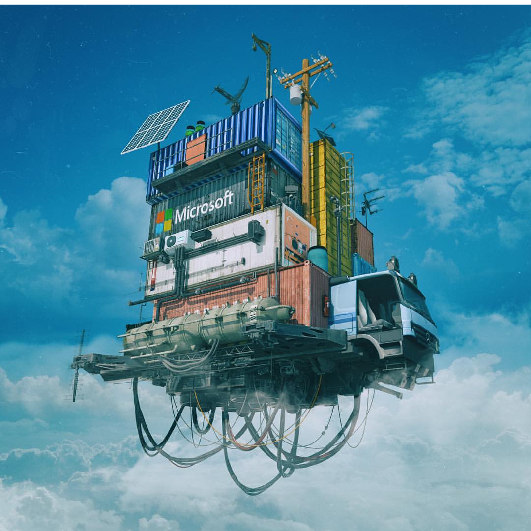
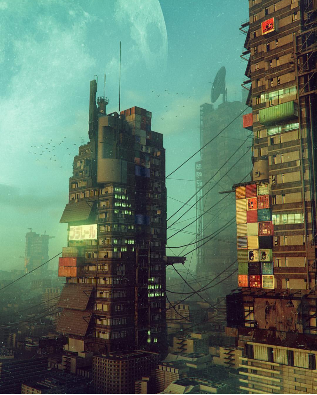
I got inspired a few weeks ago. You may have heard of a CG artist by the name of “Beeple”. His real name is Mike Winkelmann, and… well… he’s been creating one scene in 3D every day for the last 13 years! Seriously. He uses Cinema 4D primarily, and he puts out a ton of awesome work. You may even be familiar with some of it (www.beeple-crap.com; check him out). I found him by doing a Google reverse-image search of this image:
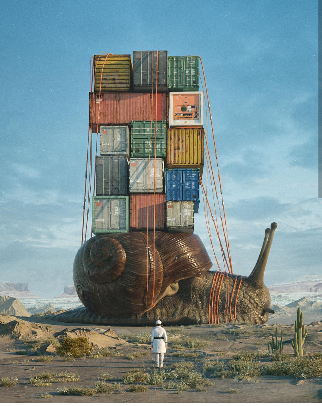
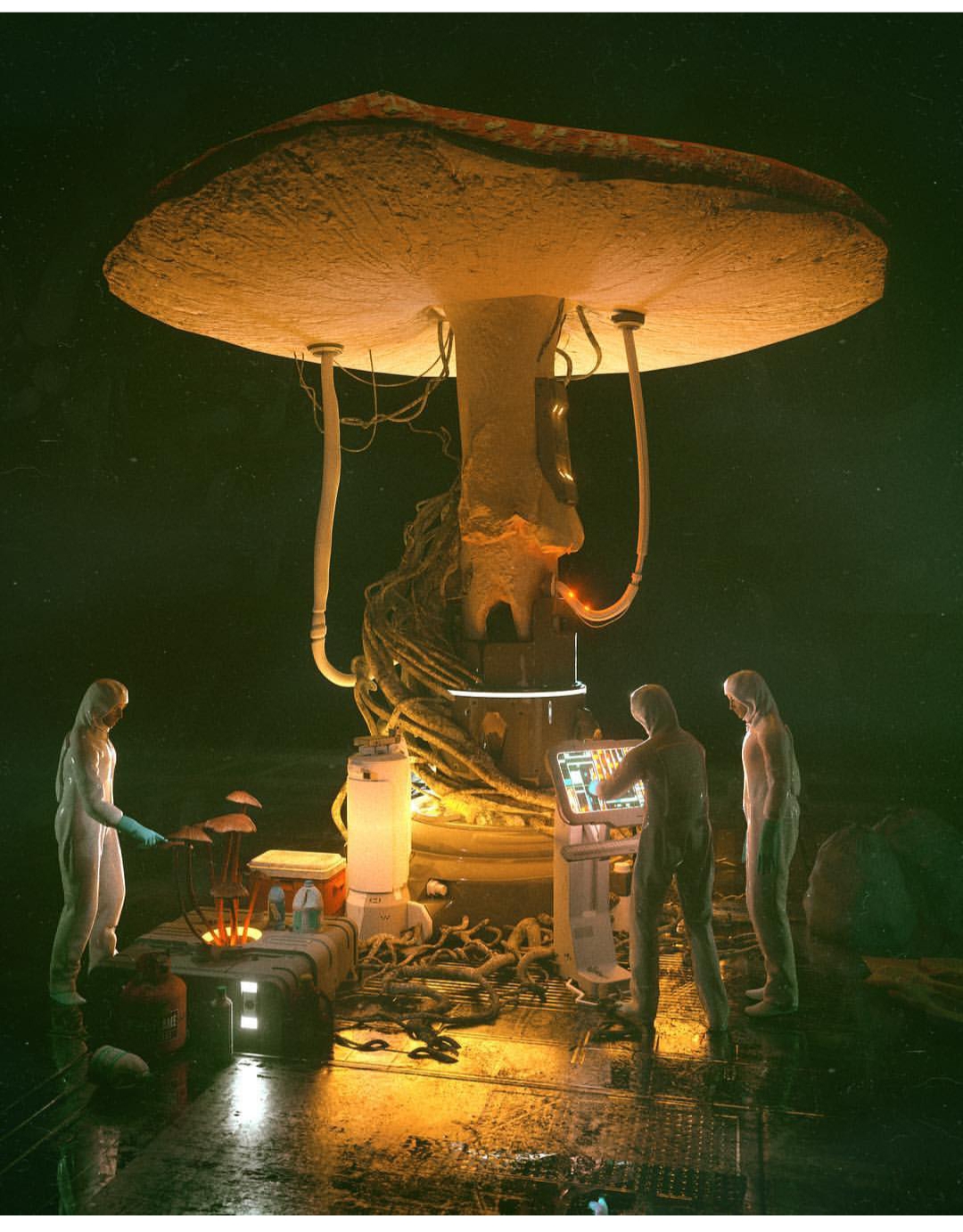
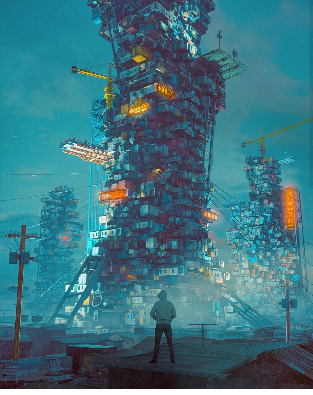
This is what started me on my journey down the trail of Beeple. This image inspired me to explore what was possible in the world of technical hard surface 3D modelling and rendering. There were quite a few things I was impressed with; primarily, the level of detail in this image was astounding. It felt very… believable. Beeple used common current-era materials to craft something completely new. Shipping containers, a bicycle, some cans, a cardboard box or two, and an air conditioning unit… these things are recognizable to the everyday layman. So when you see them stacked up into a huge post-apocalyptic Amazon truck, well, it feels more real than if the vehicle had been made up of elements that we could not recognize. Beeple has a lot of these types of images: images that are so familiar looking and matter-of-fact looking that they might as well be real. These are my 9 absolute favorites out of his 4,338 daily renders:
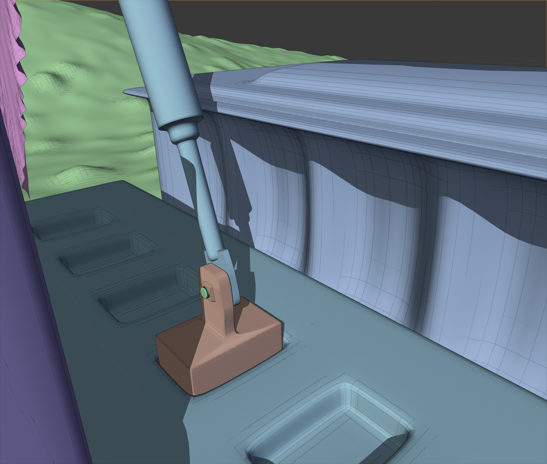
This is the kind of stuff that makes me stay up at night writing blog posts and frantically modelling increasingly complex technical nonsense. The technical detail… the accuracy… the style. It all made me want to be a technical designer or engineer all of the sudden. I realized I could learn a lot from this guy. And so, I began my first adventure into more complex hard surface 3D modelling. In Blender, I began box modelling with a subdivision surface modifier on. What does this do? Well, it allowed me to get clean, smooth surfaces and edges in my technical renders. Instead of harsh, sharp edges, I could make my objects as smooth as I wanted with much less effort. Take a look:
Modeling a Technical Piece with Subdivision Surface Modifiers
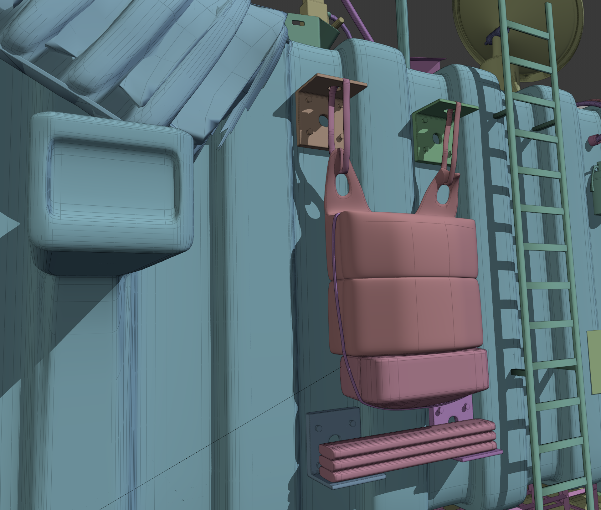
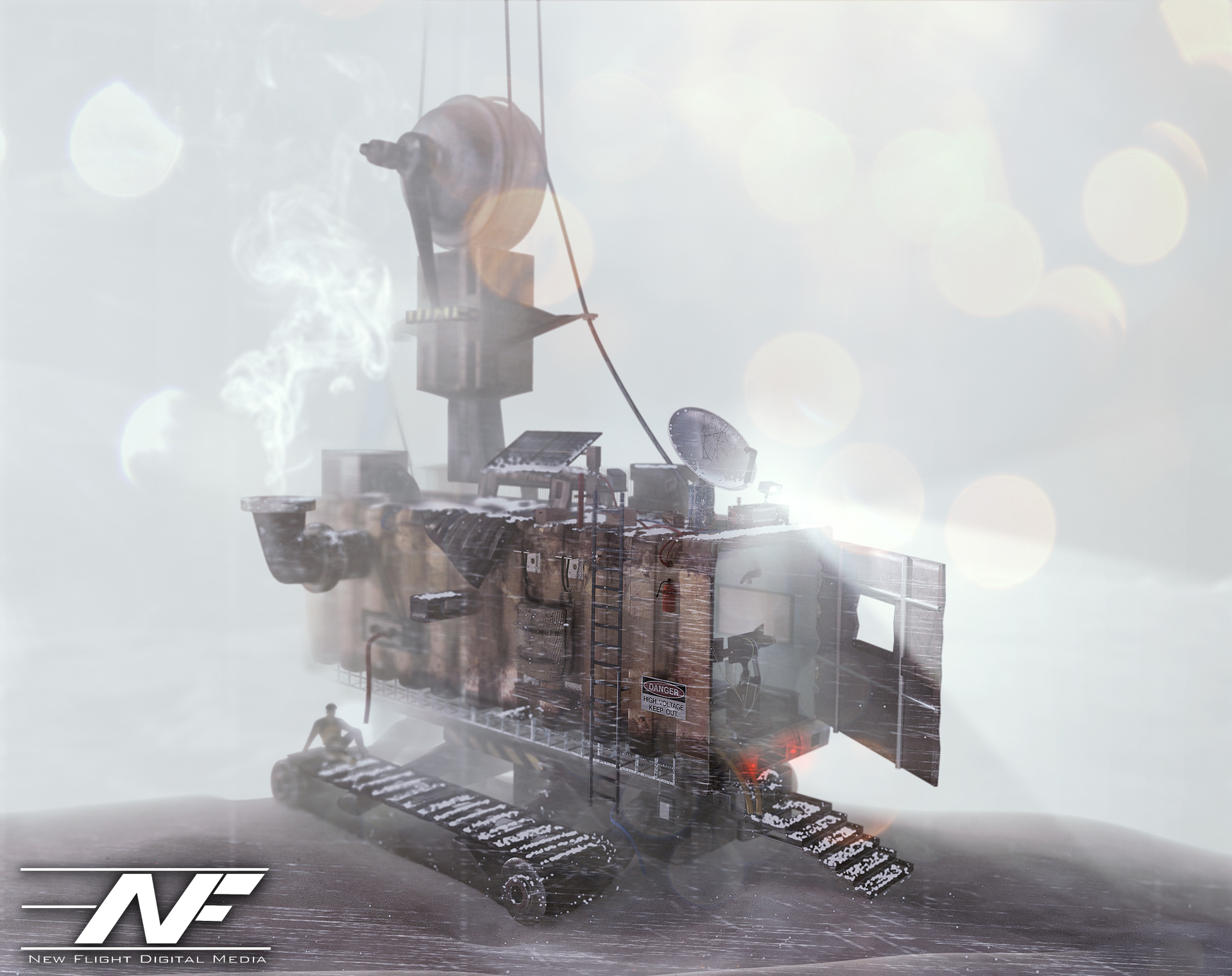
This is important because if you’ve noticed, nothing in the world is absolutely 100% sharp-edged. There is always a slight bevel or softness to an edge. The subdivision surface modifier divided and smoothed out my boxy geometry as I modeled. To get sharper edges, I would add a lateral edge loop and bring that edge closer to the exterior edge. As I did so, the exterior edge would become sharper and sharper. The result? Well, I was able to model some pretty interesting hard surfaces. Inspired by the first image I showed you, I decided to model a “tank” of sorts built out of a shipping container that might be driven in the future, perhaps. I decided to have it stranded out at a docking station, and I mentally built a story around that. I thought about where every item would go, and why it would be there. I used some particle simulations to add some snow to the shot, and took a TON of time lighting and texturing. The result? Have a look:
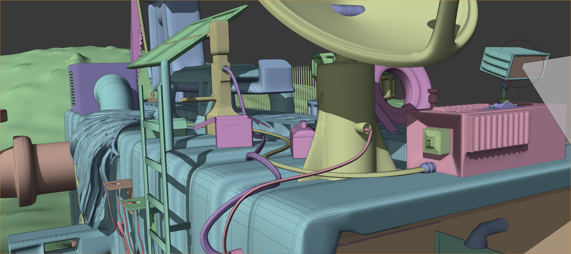
I liked where this was going. I went WAY overkill with this. I took about 3 weeks of on and off free time work to model all of the little details. Most of them aren’t even visible. For example, did you notice this flag bracket? Or these other details?
No? Well, the flag bracket was hidden from view, and those other details were hard to see. But I still modeled them. I modeled everything. There is even a fully furnished computer control area in the interior.
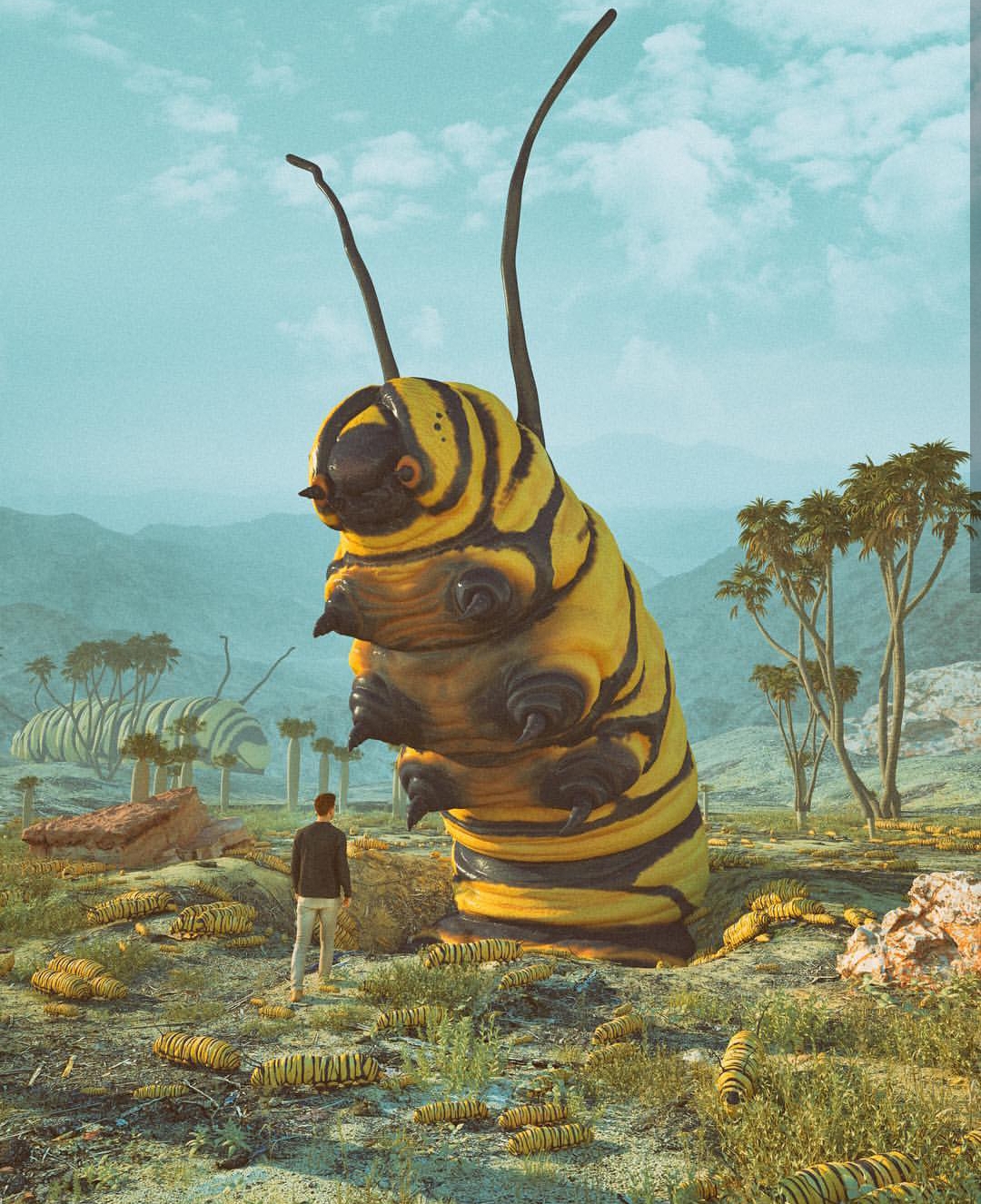
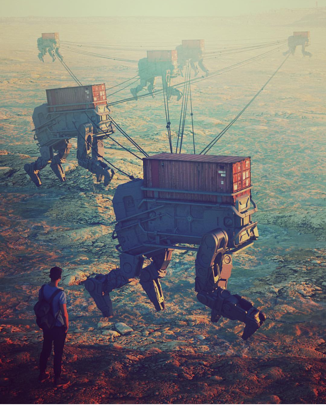
Next, I went on and did a project inspired by some of Beeple’s caterpillar images (see the gallery above). After around 2 weeks of work, I had these:
I added the human element using the open source “MakeHuman” program that I found out there on the great World Wide Web (it’s great, isn’t it?). Just like the previous image, a TON of post processing effects were done in Photoshop. Even the depth of field was done in PS using a depth pass! That’s right. See that black and white image in the Instagram gallery? I used that to define the blurriness of the image at any given point using the “Lens Blur” effect in Photoshop. Just add the depth pass as an image channel, select it in the effect dialog box, and voila! You have an automatic depth of field visualizer… in post production! I also used the depth pass as a mask for smoke effects, light flares, etc. Very useful trick.
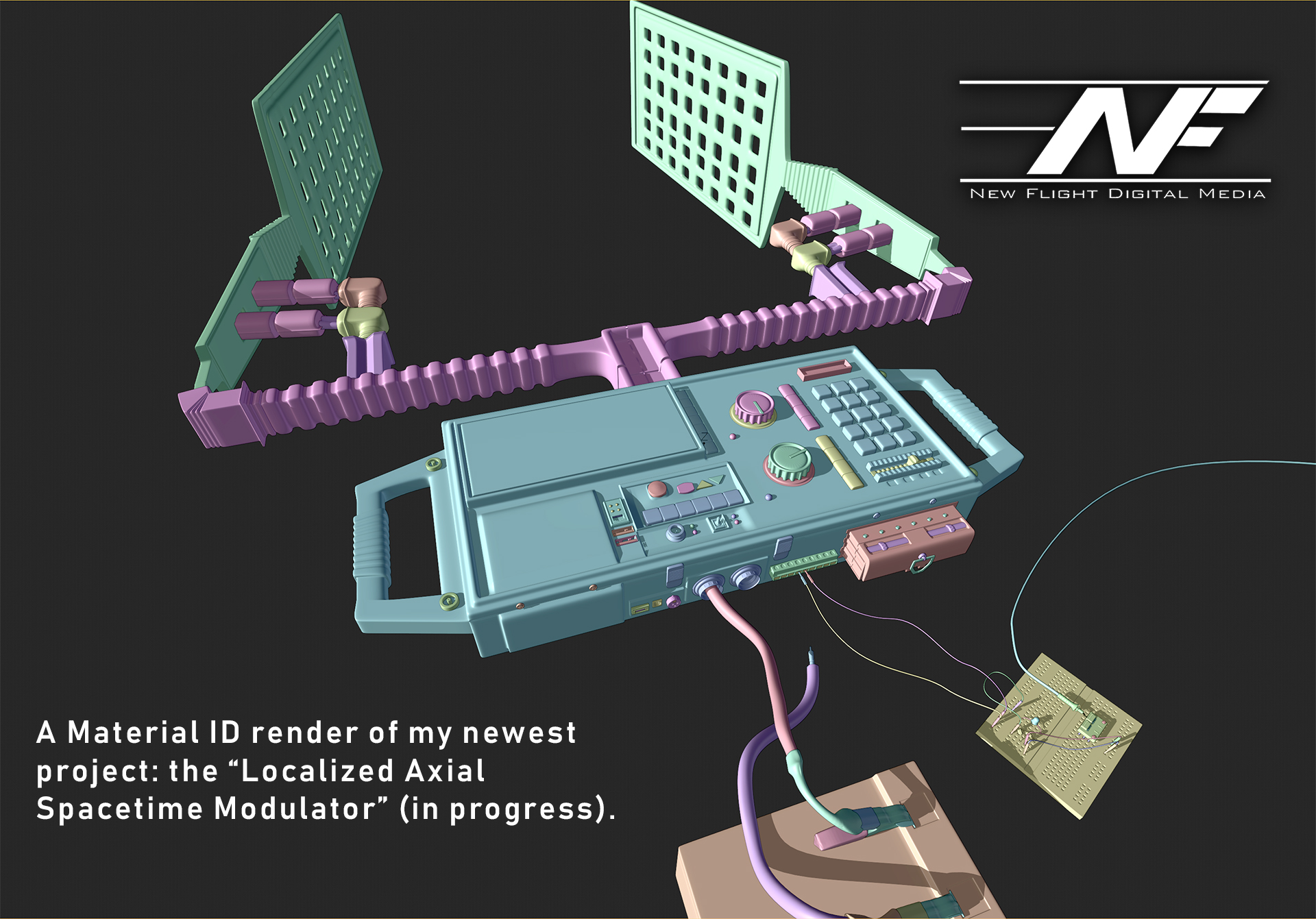
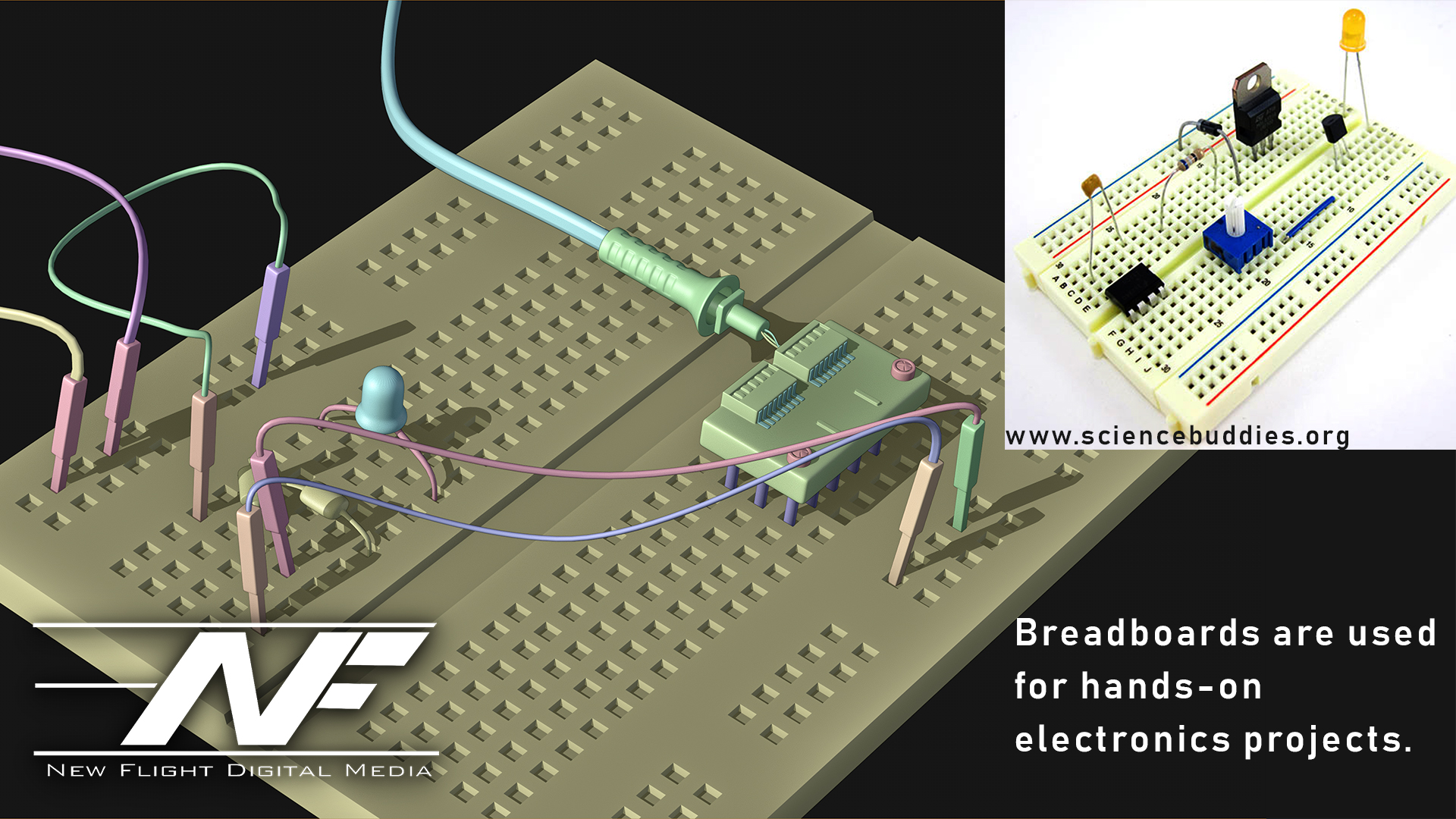
The last hard surface modelling project I’ve taken on is something… different. It is not finished yet, but I decided to model a device of some sort. I kind of went crazy on the details here. It was inspired by my pocket multi-meter sitting on my desk as I write this (a multi-meter measures a bunch of electricity stuff). I thought… what if we had a device that could warp space and time? A modulator… but for the fabric of reality (I know I’m crazy). So I came up with an idea: the “Localized Axial Spacetime Modulator”. It would use these spatula-looking antennae to warp space and time. I did a ton of background research on what this would entail so that I could make this thing look plausible. Also, just like Beeple, I added a bunch of real world elements. Sockets and materials that science-oriented people would recognize add realism to the model.
Remember… adding stuff that actually exists in the real world kind of convinces your audience that they’re looking at something real (this circuit doesn’t work by the way).
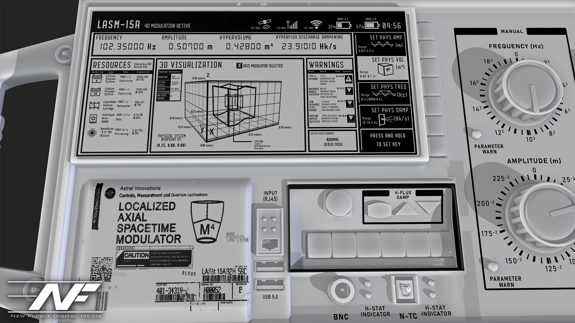
And now… the grand finale. This is my texturing I have so far: the screen of the device and the lower labels. Every part, every word and every pixel of this image has a purpose, a meaning and a reason for being there. I’m learning more and more that THAT is how you create convincing worlds: you have a why, a where, a when, a who… and fifty reasons WHY those things are the way they are.
Notice the warnings and stuff on the device, too. I got pretty creative. Some of it is common sense. The device is pretty similar to a signal generator or oscilloscope.
So… that’s all for now! If you’ve made it this far, congratulations! And Beeple, if you read this, you rock man! Go check out Beeple at www.beeple-crap.com, and head over to my site at www.newflightdigital.com to hop on my mailing list. I only send stuff out once a month on average, so you won’t get spammed. Or, shoot me an email at contact@newflightdigital.com.
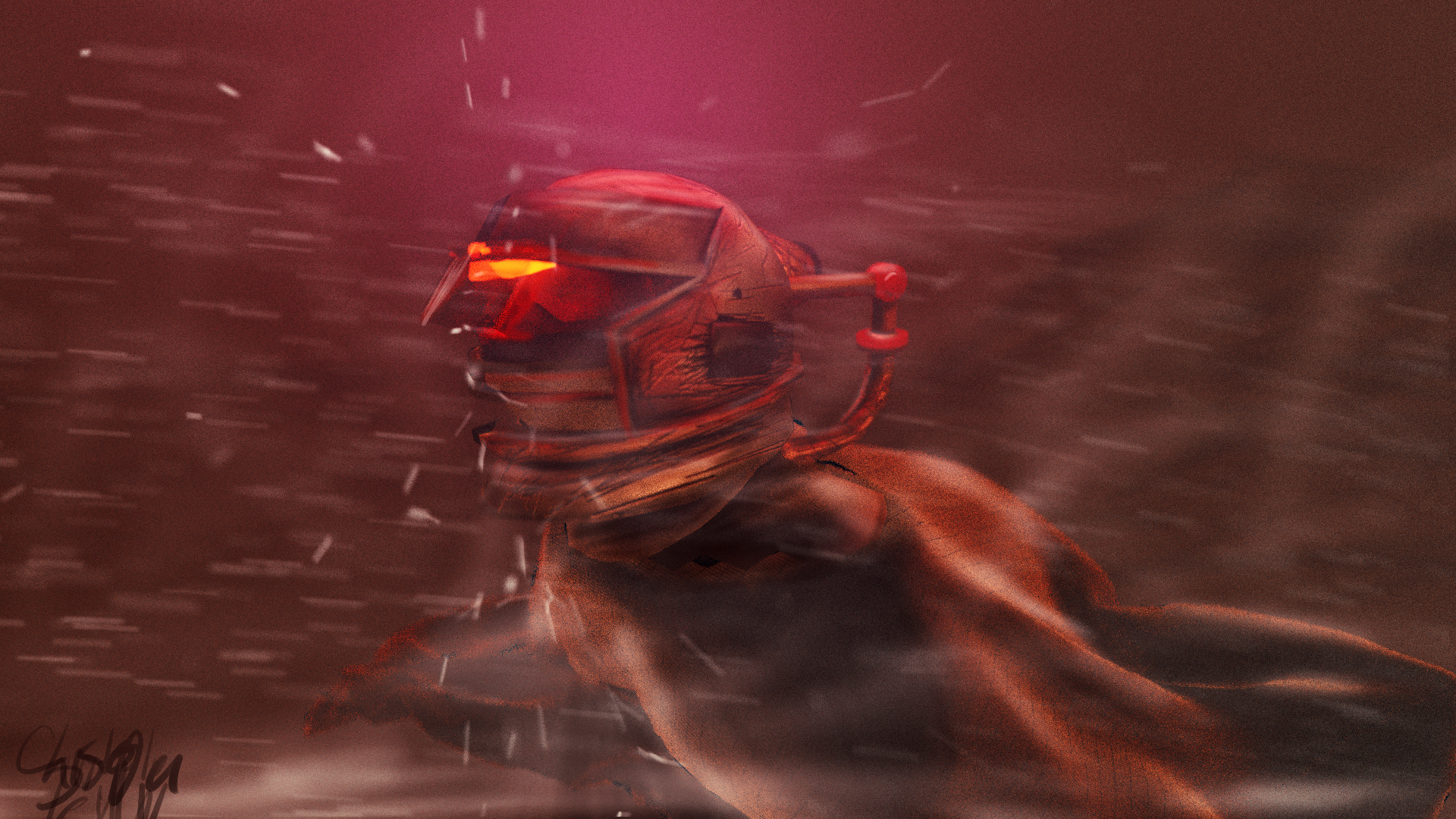
Last night, I created a set of simple concept images in roughly 4 hours of on-and-off work. My goal was to quickly develop a partial continuity between two images, establishing a sort of implied workflow utilization. In other words, I wanted to first create a hand drawn digital image of the concept using a pressure sensitive pen tablet. Then, using this drawing as a guide, I wanted to speed model and texture a 3D environment inspired by the drawing, thereby establishing a workflow continuity commonly seen in the industry: from hand drawn concept image to rendered concept image.
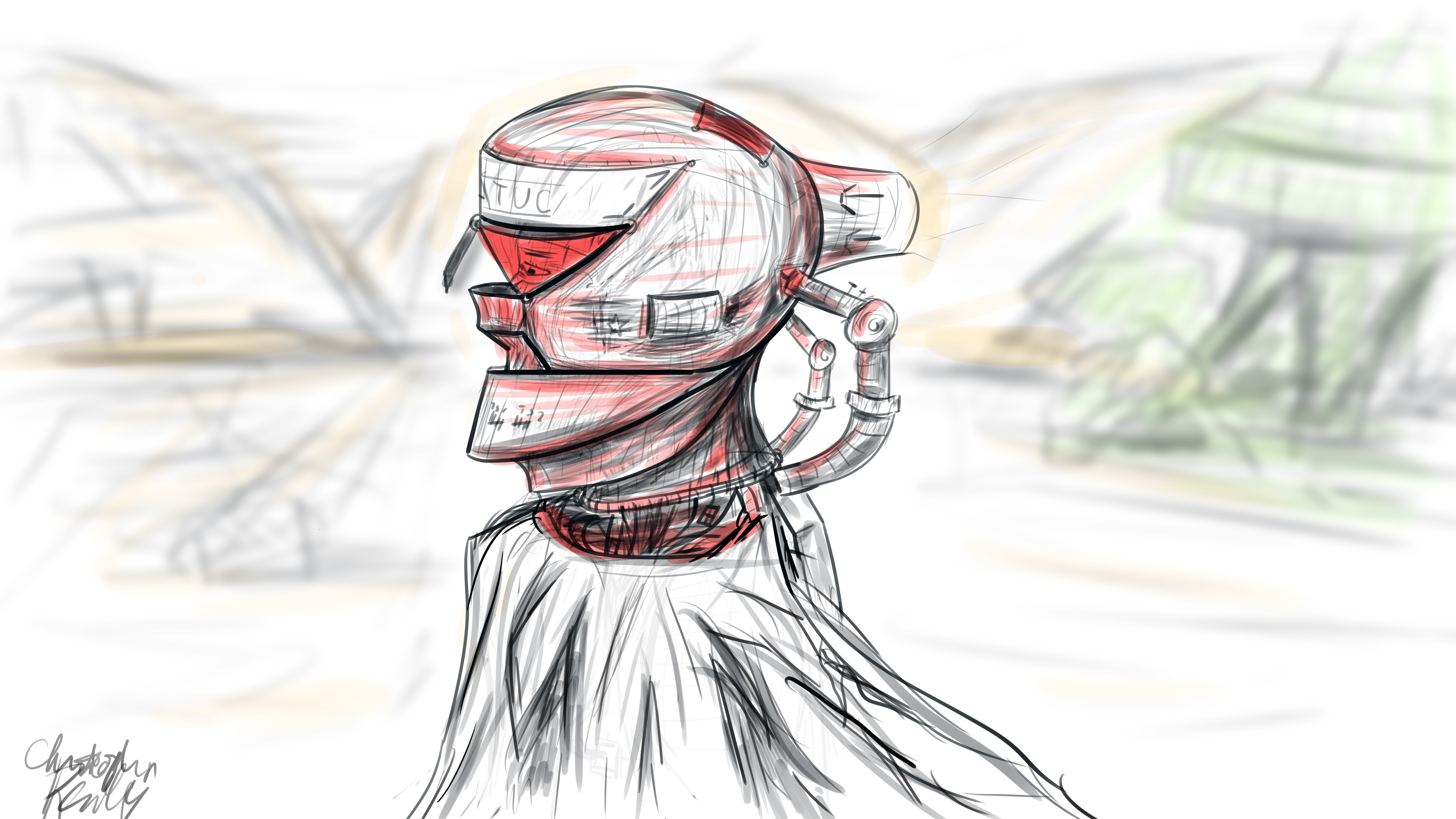
I began in Photoshop, where I set up a 16*9 inch 500 ppi resolution document with no guidelines. I set the pen size to roughly 25 pixels for fine control of the design. I decided to go for a neofuturistic, bleak image of an astronaut of some sort traversing a somewhat barren area. I wanted to combine elements of the past into the image by featuring a draped cloth, which would be covering the lower half of the figure’s visible physique. I began to draw with smoothing at around 50%. I first did a complete sketch of the man’s face from the inner muscle groups outward, even though most of this would later be covered by other elements, such as his helmet. I even included facial hair. The man’s thin face and the shape of his jaw helped dictate where the different elements of the helmet would go, and what shape they would take.
The first defining strokes I made staked out the area that would later make up the visor part of the helmet. I defined the opening that the man would be looking out of, as well as the collar piece and other essential components of the structure. Once I had pieced the entire structure together, I began shading the image according to the geometric contours using various pen widths and shapes until I was satisfied. I blocked out elements of the man’s bare face using white shapes with various opacities to define the surface of the helmet.
To go from 2D to 3D, I first sculpted the man’s bare face using the sculpting tools in Blender. I then began forming the geometric segments of the helmet around the face according to their required positions. I frequently adjusted the design and shape of the pieces on the fly as I went. When I was ready, I used Blender’s texture paint features to literally draw on color and damage marks, and applied these image textures to the model pieces in the node compositor. I used glossy shaders for the most part, and reused the hand drawn textures as displacement maps to give depth to the material.
To achieve the cloth look, I created a subdivided plane with a hole in the middle around the figure. I “pinned” the vertices at the center so that they would not move, and then ran a cloth simulation using wind and turbulence forces to achieve a billowing cloak model. I textured this using a combination of an opaque velvet shader and a transparent shader in a mix shader, with the factor set to a stretched brick texture. This gave me long strands of “cloth”, which looked like a woven burlap material up close.
I then ran a particle system with wind and a collision object to simulate snow, and rendered this separately. I pulled everything into Photoshop, applied a lookup table, touched up highlights and shadows using the brush tool, and composited dust and smoke into the shot, and rendered it out. The resulting image is comparable to the original sketch, albeit vastly different in proportion.
This exercise has given me some insight as to how concepts tend to change from conception to execution, and how one might go about adapting reference images for use in 3D environments. To see more of my work, go to www.newflightdigital.com. Feel free to reach out to me at contact@newflightdigital.com.
Over the course of the past two days, I have had the pleasure of working with the Shadow Motion Capture System to create motion capture data for characters, which will be featured in a music video. The music video takes place in a swamp, for which we are creating some creepy practical effects using a diorama. As such, the “people” performing the music will be swamp animals, created with animation and mocap data.
On set with the “Gods of Fire” during a mocap session
Without giving too much away, a frog will be singing the song, while other animals such as raccoons and lizards play the rest of the instruments. The mocap suit requires several sensors to be placed over the shoulder blades and on the chest, which often come loose during rock-out sessions. This was our biggest challenge, but we overcame that before long once we determined how to best fasten the sensors. The mocap suit transmits a 5Ghz wifi signal back to a laptop running the latest Shadow software, allowing us to record the data. To begin, we needed to have the actor strike a “T” pose, with his legs together and arms out like a T. This allowed the sensor to calibrate and determine the orientation in that pose. Once the software knew the orientation in that pose, it could determine the orientation in any other pose.
We experienced small problems with the device, but nothing too significant. For example, the device comes with foot pads that go in the user’s shoes. These pads sense pressure, and therefore, determine whether the user is in the air or not (during jumps). Since our talent was rocking out, he would often perform mini jumps in enthusiastic dance. These jumps were not enough to “trip” the pressure sensors, so they did not know the user had left the ground for a moment. As a result, the mocap figure preview on our computers would slowly slip downward as the sensors de-calibrated. The solution, of course, was to cut the jumps and replace them with other enthusiastic movements. Below, you can see our entire broadcast from yesterday when we recorded the mocap data:
All in all, the mocap session was a success. I exported each session as a BioVision Hierarchy (.bvh) file, and imported them into my favorite 3D program, Blender. To make the 3D models of the animals move, I used a plugin called MakeWalk, from http://www.makehumancommunity.com. The plugin takes BVH data and retargets it to a separate rig. To start, I produced a BVH rig for the animals using MakeHuman. The rig is one that MakeWalk can understand (since they are sister applications). I then edited the rig to fit the curvature of each animal, and then applied it to the model using automatic weights. This means that each “bone” in the rig affected a part of the model in a way that the application determined automatically. I then edited the automatic weights to better reflect the animal’s anatomy (for example, the upper arm bone should move the whole upper arm, etc.) After this, I retargeted the rig to a .bvh file recorded on set, and voila! The rig and model moved and acted just as our talent had on set. Last step was to apply “corrective smoothing” to the model to correct some bumps that inevitably form as a result of the mocap warping.
As I work on the mocap data and refine it, I will be posting more updates. Stay tuned for more… including a singing frog! That will require facial motion capture. I will be using a technique that I invented myself, and I will describe it in a future post.
If you have any questions, don’t hesitate to reach out to me at contact@newflightdigital.com.
The Xbox Kinect has long been seen as a possible tool for 3D artists and animators like myself. It has, for so long, been contemplated as a tool for both motion capture (Mocap), and for Photogrammetric scanning (3D reconstruction of complex environments). I took the liberty of testing a variety of Kinect techniques. What works? What doesn’t?
We will start with the bad: the Kinect suffers outdoors. Plagued by UV and IR interference, the Kinect cannot see past a few feet outdoors on a sunny day. We tested the Kinect while having it running pointed out the back of a moving vehicle, planning on using the Kinect as a tool to reconstruct a neighborhood in 3D, but due to the bumpy and dark asphalt surface in front of it, infrared light was easily absorbed, and the Kinect could not even reconstruct the road for this test. Its range was reduced to only a few feet. When stationary, the Kinect’s range extended to around 15 feet when pointed at a free standing object. We also tested the Kinect as a tool for scanning the facades of houses. I used a program called Brekel PointCloud to capture a pointcloud sequence of the house as I moved around it. The software captured a sequence of 3D mesh files, which were converted into an .obj sequence and manually reconstructed in Blender. This gave us mixed, partial results:
Brekel Pointcloud does provide a unique opportunity, however. Using the program, one can create 3D sequences, exported either as Alembic (.abc) or .obj sequences. Lets’s suppose, as a VFX artist, you wanted actors to interact with a 3D flood of water, created in post-production with a fluid simulation. With a Kinect, this should, in theory, be easier, as the actors could be captured in 3D by the Kinect, allowing the animated 3D mesh to be used as an obstacle object in the fluid simulation. In our tests, the alembic files created by Brekel did not work as collision objects in Blender’s fluid simulation, but I will update as we think of new ideas in the area.
Moving on to another Kinect program known as Kinect Fusion, the prospects of the Kinect as a stationary photogrammetry device become slightly better. In the video below, observe our efforts in the area. The Kinect is capable of producing a high-poly, low quality 3D mesh of the environment:
This brings a similar idea to mind. If animations of 3D objects captured with the Kinect cannot be used in fluid simulations, perhaps static ones can. This idea checks out, although we have not completed a full test. In theory, one could use the mesh output from Kinect Fusion as a collision object in a fluid simulation, and save a lot of time modelling the room. In fact, in the fast-paced, often rushed schedule of a 3D artist, this could save time and money. I will study this application further.
Outside of the realm of photogrammetry, the Kinect works well as a medium-quality motion capture device. Using Brekel ProBody, I was able to produce convincing .bvh files, imported into Blender:
I will elaborate on Motion Capture with the Kinect in a future blog post.