Enhancing Autumn Cinematography with the Power of After Effects 3D

This season I had the opportunity to do something I haven’t done in a while: seasonal nature cinematography! Depending on who you ask, nature cinematography can be inspiring, frustrating, calming, or anything in between. For me, it was an opportunity to combine some traditional filmmaking techniques with some After Effects magic. Using After Effects expressions, effects, and 3D camera tracking, you can turn your cinematography shots into entirely new, ethereal autumnal scenes! If you haven’t seen the video yet, check it out:

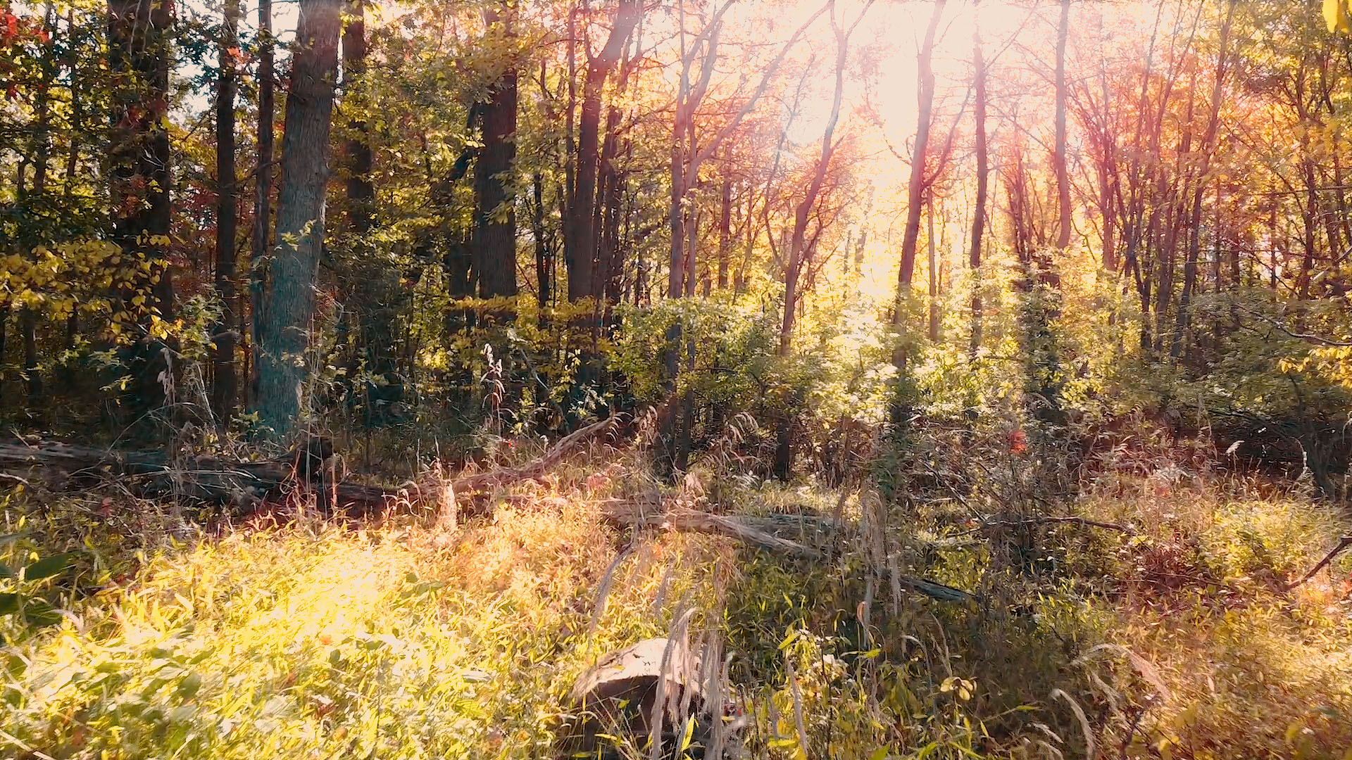
The first trick I thought of was using After Effects 3D camera tracking to add “god rays” to forest imagery. This volumetric trick allows you to render streaks of light appearing from in between branches, leaves, etc. to give your shots some atmospheric realism. We can get the origin of the rays to remain the same thanks to After Effects’s 3D features!

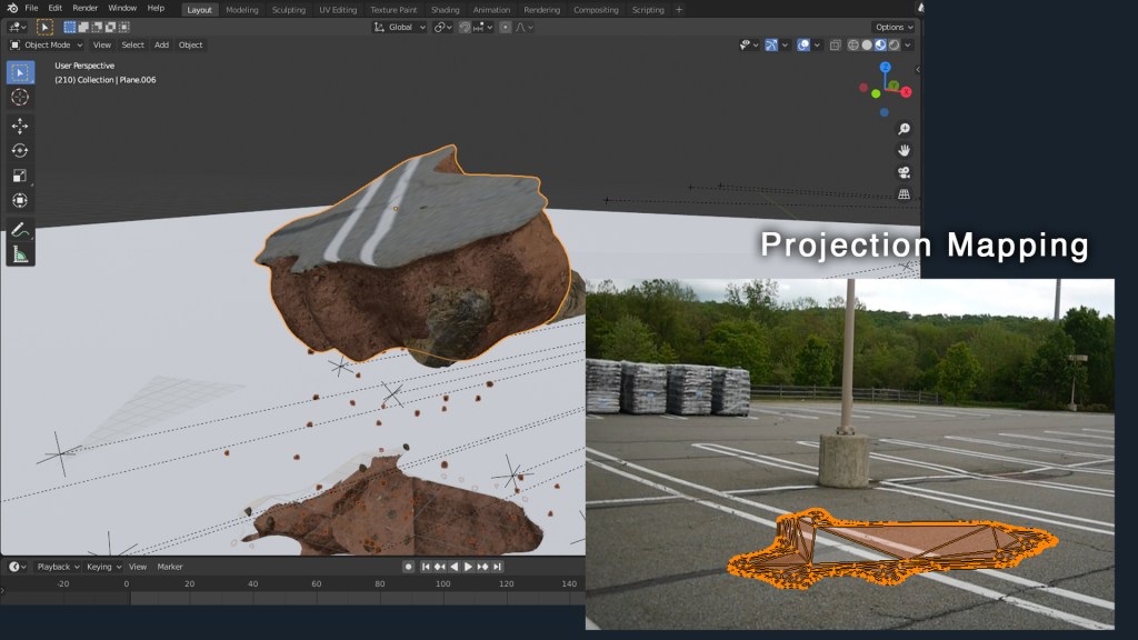
First, prep your footage. Get it into the lowest frame rate you’re comfortable with (shouldn’t be under 24FPS). Next, track your footage with AE’s camera solver. This is automatic, so it shouldn’t involve much more than just pressing the button, sitting back and waiting!

After the track is done, select the camera track effect in the effects panel, hover over the footage, and you’ll see some 3D markers. Right click on the spot in the image where the god rays would be coming from, and click “Add Null and Camera”. This will plop a null object right in 3D space where the light is coming from; scrub through the timeline and you’ll see it stays in the same spot. Perfect!

Now, how to get those rays? First, duplicate the footage layer, and apply a radial blur effect. Set it to a zoom mode and adjust the amount until you see a streaky semblance of your image. Then, alt+click on the center point icon (little target). This will allow you to write an expression to tell AE where to put the center point. We’re going to tell AE to use the 2D screenspace that corresponds to the 3D null object’s location. To do this, paste this code as the expression (but change the values for your footage):

src = thisComp.layer('Null'); // Enter the name of the Null you made
src.toComp([0,0,0]);

Next, we only want the streaks to show up when the part of the screen where the light is coming from is bright. Otherwise, the light is probably blocked by a branch, etc. We can tell AE to adjust the opacity of the streaky layer according to the brightness of a certain part of the screen! Alt+click on the “opacity” timer icon, and paste this code in as the expression:

area = comp("NameOfShot").layer("NameOfLayer");  //Enter name of your comp shot, and name of the layer.
sample = [960,260]; //This is the location in the image you want to sample.
sampleArea = [50,50]; //This is how much area around that target you want to sample.
luminance = rgbToHsl(target.sampleImage(sample,sampleArea))[2];
linear(lum, 0, 1, 50, 100)

That code will adjust the opacity according to the brightness of an area of the screen of your choosing. Finally, just change the blending mode of the streaky layer to “Add” or “Screen” so you only get the bright parts of the image, and (after a bunch of tweaking of values), you’re done! You’ll also want to add a “curves” effect to the streaky layer to control the sharpness of the rays.

Before & After (Slide)

I hope you enjoyed this little After Effects tip; we’re open for custom work, animation, visual effects and more! Visit www.newflightdigital.com for more info.

Creating the CGI Music Video for Adhesive Wombat’s “Storm Crusher”

Recently, I had the opportunity to produce a CGI/visual effects-based music video for AdhesiveWombat, an electronic music creator on SoundCloud, YouTube and the like. If you’re into tech, you may even know him as the producer of the “theme song” for Linus Tech Tips’s “WAN Show“. Well, that “theme song”, AKA “Storm Crusher”, got an animated, VFX music video addition this summer! Using a suite of 3D software and compositing tools, I put together a VFX adventure for this track with the help of some live action footage, photorealistic raytracing, and particle simulations! If you haven’t see it yet, check it out!

Adhesive Wombat’s “Storm Crusher”

This video involved many production and post production processes, but I’d like to highlight a few. For this video to work, you’ll notice that the music needed to “drive” the animation in some parts. I used a script to convert certain frequencies from the sound track (typically between 0 and 4 KHz), into usable animation data that could be manicured, amplified, and turned into pulsations, movement, and force field data for particle animations.

Here, you can see the pulsating orb and its particles from the beginning, alongside a graph visualization displaying several parameters driven by the sound from the music. You’ll also notice the music track along the top of the viewport… super useful when you want to match the movements up just right! Here’s another example of the orb, along with its graph view (showing several channels of displacement data driven by sound):

To complete this video, I needed to use “projection mapping”. That is, I needed to partially reconstruct some environments in 3D, and project imagery onto them in order to ensure that the 3D objects in the scene would conform to the lighting situation when the video was shot. Here’s an example of partially re-projecting a building onto a rough box model:

This allows for so many possibilities. Water, for example (of which there is a lot in this video), has a refractive index (the extent to which light is bent when it passes through the object). This means that material needs to be present behind the object so that there is something to “see” through the water when the light gets bent through it. Using this technique, I can recreate real world lighting conditions (with the help of an HDRI backdrop).

Here, you can see how this is accomplished… a mesh’s geometry is “projected” from the tracked camera’s point of view, and the imagery in that scene is applied. This allows me to make actual “chunks” of the parking lot rip apart!

Finally, I’d like to discuss those clouds. The clouds were produced procedurally using dynamic noise mixed with a black/white 3D mask to “guide” the clouds to where they needed to appear (the mask was animated to “steer” the clouds to different areas). You can see how the clouds only appear in a small area, although the mesh is much larger:

These clouds used volumetric materials, meaning that what you see is a subset of the mesh’s volume, rather than its surface. Raytracing render engines are needed to accomplish this, since the light bounces (the paths that the light takes) through the clouds need to be calculated by the computer. Using this technique, you can also get some really crisp volumetric shadows from other objects in the scene, like in the one above, for example. When that chunk of dirt comes out of the field, the crisp shadow edges on the volumetrics certainly help “sell” the effect.

Overall, this was such a blast! I’m glad everyone seems to like the results. Super, super special thanks to AdhesiveWombat for allowing me to bring his already legendary music a visual counterpart. Please go follow him, etc:

AdhesiveWombat’s Socials:

New Flight Digital’s Socials:

Want to get in touch? Visit newflightdigital.com!

Designing a Website with Total Creative Control: Building the Improved ‘New Flight’ Website

Whether you own a business, need to promote yourself, or run a nonprofit, owning a website that suffers from bad web design is a terrible disadvantage. The first New Flight Digital website was designed in Adobe Muse, a now-discontinued WYSIWYG (what you see is what you get) website designer. I knew there were many disadvantages to using such a program (less creative freedom, lack of direct control over content, etc), but like so many others, I simply lacked the know-how to launch into building my own website from scratch. Until I started Googling… and googling… and googling…

I knew a revamped New Flight website would need to showcase some of our products, and the many eye catching 3D graphics and effects we have produced. It would need to be big, bold and colorful, like the company. I started looking to other similar (albeit larger-name) players in the VFX industry for inspiration. Digital Domain, for example, has a front page with pleasing motion graphics, large hero-shots of their work, and a unified color scheme.

Digital Domain’s website includes attractive features and large imagery

With next to no idea where to begin, I started with an open source HTML template and opened it in Adobe Dreamweaver. Quick, rapid google searches were my go-to as I learned the ins and outs of HTML and CSS. But I soon realized that the things I wanted to display on the website could not be accomplished with HTML alone. You see, websites like the one I had in mind are the result of the interplay between HTML and CSS files, Javascript, PHP, and other elements, all interacting. The latter two are scripts… files that are intended to execute in order to accomplish something. In order to execute PHP, I needed to set up a web server, since PHP runs on the server itself. Try to view a “.php” file without hosting it on a web server, and it won’t do anything, because there’s no server to run it. Javascript on the other hand executes “client side”, meaning it executes in the viewer’s browser, and not on the server.

  • PHP- Server-side code (script)
  • Javascript- Client-side code (script)
  • HTML- What web pages are ultimately made of
  • CSS- Cascading Style Sheet; how web pages know what to look like

After setting up a local testing environment with XAMPP, I quickly mocked up some design ideas. Any files I edited and saved would automatically update on the web server, since I was editing them directly. This was extremely useful for up-to-the-moment updated views of the website code. I knew I needed some 3D elements on the website. After all, that’s what we do. Why not have some cool 3D objects for the user to interact with? For this, after some googling, I used three.js, a 3D Javascript library. Think of it like a set of files that allows you to create 3D scenes in Javascript. I dug in, and spent months working on a front page 3D scene using Blender to create assets.

Three.js is an incredible library behind some impressive web design

But there was so much more! I needed a contact form, a downloads page, a blog slider, and other elements. For all of them, I either used PHP or Javascript to deliver the information to the viewer. If a script needed direct access to server elements, I used PHP, since it ran on the server, and therefore could access the server files. If something needed to be rendered by the client, I used Javascript, since it ran on the user’s computer.

The front page of http://www.newflightdigital.com

In the coming months, I hope to share details of how I accomplished certain aspects of my website. All it took was googling… and patience. If you have those two things, you can create an entire website without costly alternatives, and have complete control over how it operates, what it does, and everything in between. Leave some comments below about what element of the new website you would like explained, or shoot an email to contact@newflightdigital.com.

Processing…
Success! You're on the list.

Artistic Hard Surface Modelling: Creating Realistic Looking, Fictional Technical Art (Blender and Photoshop)

I got inspired a few weeks ago. You may have heard of a CG artist by the name of “Beeple”. His real name is Mike Winkelmann, and… well… he’s been creating one scene in 3D every day for the last 13 years! Seriously. He uses Cinema 4D primarily, and he puts out a ton of awesome work. You may even be familiar with some of it (www.beeple-crap.com; check him out). I found him by doing a Google reverse-image search of this image:

Image courtesy: Mike Winkelmann, of course.
http://www.beeple-crap.com

This is what started me on my journey down the trail of Beeple. This image inspired me to explore what was possible in the world of technical hard surface 3D modelling and rendering. There were quite a few things I was impressed with; primarily, the level of detail in this image was astounding. It felt very… believable. Beeple used common current-era materials to craft something completely new. Shipping containers, a bicycle, some cans, a cardboard box or two, and an air conditioning unit… these things are recognizable to the everyday layman. So when you see them stacked up into a huge post-apocalyptic Amazon truck, well, it feels more real than if the vehicle had been made up of elements that we could not recognize. Beeple has a lot of these types of images: images that are so familiar looking and matter-of-fact looking that they might as well be real. These are my 9 absolute favorites out of his 4,338 daily renders:

This is the kind of stuff that makes me stay up at night writing blog posts and frantically modelling increasingly complex technical nonsense. The technical detail… the accuracy… the style. It all made me want to be a technical designer or engineer all of the sudden. I realized I could learn a lot from this guy. And so, I began my first adventure into more complex hard surface 3D modelling. In Blender, I began box modelling with a subdivision surface modifier on. What does this do? Well, it allowed me to get clean, smooth surfaces and edges in my technical renders. Instead of harsh, sharp edges, I could make my objects as smooth as I wanted with much less effort. Take a look:

Modeling a Technical Piece with Subdivision Surface Modifiers

This is important because if you’ve noticed, nothing in the world is absolutely 100% sharp-edged. There is always a slight bevel or softness to an edge. The subdivision surface modifier divided and smoothed out my boxy geometry as I modeled. To get sharper edges, I would add a lateral edge loop and bring that edge closer to the exterior edge. As I did so, the exterior edge would become sharper and sharper. The result? Well, I was able to model some pretty interesting hard surfaces. Inspired by the first image I showed you, I decided to model a “tank” of sorts built out of a shipping container that might be driven in the future, perhaps. I decided to have it stranded out at a docking station, and I mentally built a story around that. I thought about where every item would go, and why it would be there. I used some particle simulations to add some snow to the shot, and took a TON of time lighting and texturing. The result? Have a look:

I liked where this was going. I went WAY overkill with this. I took about 3 weeks of on and off free time work to model all of the little details. Most of them aren’t even visible. For example, did you notice this flag bracket? Or these other details?

No? Well, the flag bracket was hidden from view, and those other details were hard to see. But I still modeled them. I modeled everything. There is even a fully furnished computer control area in the interior.

Next, I went on and did a project inspired by some of Beeple’s caterpillar images (see the gallery above). After around 2 weeks of work, I had these:

I added the human element using the open source “MakeHuman” program that I found out there on the great World Wide Web (it’s great, isn’t it?). Just like the previous image, a TON of post processing effects were done in Photoshop. Even the depth of field was done in PS using a depth pass! That’s right. See that black and white image in the Instagram gallery? I used that to define the blurriness of the image at any given point using the “Lens Blur” effect in Photoshop. Just add the depth pass as an image channel, select it in the effect dialog box, and voila! You have an automatic depth of field visualizer… in post production! I also used the depth pass as a mask for smoke effects, light flares, etc. Very useful trick.

The last hard surface modelling project I’ve taken on is something… different. It is not finished yet, but I decided to model a device of some sort. I kind of went crazy on the details here. It was inspired by my pocket multi-meter sitting on my desk as I write this (a multi-meter measures a bunch of electricity stuff). I thought… what if we had a device that could warp space and time? A modulator… but for the fabric of reality (I know I’m crazy). So I came up with an idea: the “Localized Axial Spacetime Modulator”. It would use these spatula-looking antennae to warp space and time. I did a ton of background research on what this would entail so that I could make this thing look plausible. Also, just like Beeple, I added a bunch of real world elements. Sockets and materials that science-oriented people would recognize add realism to the model.

Remember… adding stuff that actually exists in the real world kind of convinces your audience that they’re looking at something real (this circuit doesn’t work by the way).

And now… the grand finale. This is my texturing I have so far: the screen of the device and the lower labels. Every part, every word and every pixel of this image has a purpose, a meaning and a reason for being there. I’m learning more and more that THAT is how you create convincing worlds: you have a why, a where, a when, a who… and fifty reasons WHY those things are the way they are.

Notice the warnings and stuff on the device, too. I got pretty creative. Some of it is common sense. The device is pretty similar to a signal generator or oscilloscope.

So… that’s all for now! If you’ve made it this far, congratulations! And Beeple, if you read this, you rock man! Go check out Beeple at www.beeple-crap.com, and head over to my site at www.newflightdigital.com to hop on my mailing list. I only send stuff out once a month on average, so you won’t get spammed. Or, shoot me an email at contact@newflightdigital.com.

Creating a Futuristic Concept Scene: Speed Designing with Photoshop and Blender

Last night, I created a set of simple concept images in roughly 4 hours of on-and-off work. My goal was to quickly develop a partial continuity between two images, establishing a sort of implied workflow utilization. In other words, I wanted to first create a hand drawn digital image of the concept using a pressure sensitive pen tablet. Then, using this drawing as a guide, I wanted to speed model and texture a 3D environment inspired by the drawing, thereby establishing a workflow continuity commonly seen in the industry: from hand drawn concept image to rendered concept image.

I began in Photoshop, where I set up a 16*9 inch 500 ppi resolution document with no guidelines. I set the pen size to roughly 25 pixels for fine control of the design. I decided to go for a neofuturistic, bleak image of an astronaut of some sort traversing a somewhat barren area. I wanted to combine elements of the past into the image by featuring a draped cloth, which would be covering the lower half of the figure’s visible physique. I began to draw with smoothing at around 50%. I first did a complete sketch of the man’s face from the inner muscle groups outward, even though most of this would later be covered by other elements, such as his helmet. I even included facial hair. The man’s thin face and the shape of his jaw helped dictate where the different elements of the helmet would go, and what shape they would take.

The first defining strokes I made staked out the area that would later make up the visor part of the helmet. I defined the opening that the man would be looking out of, as well as the collar piece and other essential components of the structure. Once I had pieced the entire structure together, I began shading the image according to the geometric contours using various pen widths and shapes until I was satisfied. I blocked out elements of the man’s bare face using white shapes with various opacities to define the surface of the helmet.

To go from 2D to 3D, I first sculpted the man’s bare face using the sculpting tools in Blender. I then began forming the geometric segments of the helmet around the face according to their required positions. I frequently adjusted the design and shape of the pieces on the fly as I went. When I was ready, I used Blender’s texture paint features to literally draw on color and damage marks, and applied these image textures to the model pieces in the node compositor. I used glossy shaders for the most part, and reused the hand drawn textures as displacement maps to give depth to the material.

To achieve the cloth look, I created a subdivided plane with a hole in the middle around the figure. I “pinned” the vertices at the center so that they would not move, and then ran a cloth simulation using wind and turbulence forces to achieve a billowing cloak model. I textured this using a combination of an opaque velvet shader and a transparent shader in a mix shader, with the factor set to a stretched brick texture. This gave me long strands of “cloth”, which looked like a woven burlap material up close.

I then ran a particle system with wind and a collision object to simulate snow, and rendered this separately. I pulled everything into Photoshop, applied a lookup table, touched up highlights and shadows using the brush tool, and composited dust and smoke into the shot, and rendered it out. The resulting image is comparable to the original sketch, albeit vastly different in proportion.

This exercise has given me some insight as to how concepts tend to change from conception to execution, and how one might go about adapting reference images for use in 3D environments. To see more of my work, go to www.newflightdigital.com. Feel free to reach out to me at contact@newflightdigital.com.

Home Automation Scripting with the Raspberry Pi: Update #1

Over the past year, I have experimented with different methods of home automation, from scripts that automatically render my projects for me, to light control. In this time, I have been using an old E-machines desktop computer with a failing hard disk and limited RAM. Well, this holiday season, the thing finally gave out on me, but luckily I had a spare Raspberry Pi to fill this void. I transferred the necessary scripts that I had written, as well as the necessary programs that I had found online and compiled. The current system has my Pi mounted to a wall on one end of my room with a status monitor, connected to a very long USB cable which snakes around the perimeter of my room to the opposite wall. There, the USB cable is connected to a USB hub which connects to a USB-DMX dongle (to control RGB lights), and a USB relay module to control a tower light and buzzer set for special alert cases. The whole thing is controlled by a script that checks a Google Firebase database every 5 seconds for changes. I have created an Android app using MIT App Inventor which communicates with the same Firebase database, thereby communicating with the Raspberry Pi over the internet. With this setup, I can change the color of my room lights, tell the Raspberry Pi to say a specific phrase, and more. To date, my home automation system is equipped with the following abilities:

  • A briefing program, which uses Linux’s “espeak” text to speech terminal program to address me and give me updates on the status of various processes. For this program, the script first gathers various statistics by loading up various web pages, saving them into text documents, and parsing them. For example, the briefing program provides the weather, temperature, the number of followers on each of my social media accounts, as well as more personalized data such as the number of files rendered over night.
  • A continuous social media checker, which alerts me when I gain or loose a follower on Instagram by telling me verbally and by turning the LEDs in my room either green or red.
  • Full LED lighting control via a USB-DMX interface, and a strip of RGB LEDs connected to a DMX decoder.
  • A facial recognition program that uses a webcam connected to the Pi, complete with a full login and logout system, which can recognize a person entering the room and identify them, setting the room state to their preference.
  • A custom phrase repeater, which gets its phrase from the Android app.
  • A custom alarm clock which will read input from my app, setting an alarm for the appropriate time and waking up the room occupant at the appropriate time using voice features.
  • And much more!
On the left, the wall mounted black box is the Pi. The screen above it will soon display statistics, current system state information, and security data.

As I mentioned above, the two main complex connections involved with this setup are the USB relay module, and the USB-DMX interface. I managed to find open source command line programs for Linux online to control both the USB relay module and the USB-DMX interface. Just pure luck! Below are images of both interfaces.

A USB cable from the hub connected to the Pi connects to the USB-DMX interface, which plugs into this DMX decoder, which then receives power from the left and splits the signal into the appropriate RGB channels for the lights.
A USB cable from the hub connects to this relay module, which receives power from the left. According to the signals received from the Pi, the relay module will open or close the relays, thereby turning on or off the different components on the tower light.
This is the tower light, which includes a buzzer and 3 lights.

Above, you can see a screenshot from the light controller portion of my app, and some of the lighting options.

This has been a very, very brief overview of the system. Parts of it, such as the facial recognition system and the relay control, took many days to set up and get working properly. If you would like to know more, leave a comment requesting a future blog topic!

Motion Capture for Music Videos: Update #1

Over the course of the past two days, I have had the pleasure of working with the Shadow Motion Capture System to create motion capture data for characters, which will be featured in a music video. The music video takes place in a swamp, for which we are creating some creepy practical effects using a diorama. As such, the “people” performing the music will be swamp animals, created with animation and mocap data. 

Practical Effects created with a Swamp Diorama
On set with the “Gods of Fire” during a mocap session

Without giving too much away, a frog will be singing the song, while other animals such as raccoons and lizards play the rest of the instruments. The mocap suit requires several sensors to be placed over the shoulder blades and on the chest, which often come loose during rock-out sessions. This was our biggest challenge, but we overcame that before long once we determined how to best fasten the sensors. The mocap suit transmits a 5Ghz wifi signal back to a laptop running the latest Shadow software, allowing us to record the data. To begin, we needed to have the actor strike a “T” pose, with his legs together and arms out like a T. This allowed the sensor to calibrate and determine the orientation in that pose. Once the software knew the orientation in that pose, it could determine the orientation in any other pose. 

We experienced small problems with the device, but nothing too significant. For example, the device comes with foot pads that go in the user’s shoes. These pads sense pressure, and therefore, determine whether the user is in the air or not (during jumps). Since our talent was rocking out, he would often perform mini jumps in enthusiastic dance. These jumps were not enough to “trip” the pressure sensors, so they did not know the user had left the ground for a moment. As a result, the mocap figure preview on our computers would slowly slip downward as the sensors de-calibrated. The solution, of course, was to cut the jumps and replace them with other enthusiastic movements. Below, you can see our entire broadcast from yesterday when we recorded the mocap data:

All in all, the mocap session was a success. I exported each session as a BioVision Hierarchy (.bvh) file, and imported them into my favorite 3D program, Blender. To make the 3D models of the animals move, I used a plugin called MakeWalk, from http://www.makehumancommunity.com. The plugin takes BVH data and retargets it to a separate rig. To start, I produced a BVH rig for the animals using MakeHuman. The rig is one that MakeWalk can understand (since they are sister applications). I then edited the rig to fit the curvature of each animal, and then applied it to the model using automatic weights. This means that each “bone” in the rig affected a part of the model in a way that the application determined automatically. I then edited the automatic weights to better reflect the animal’s anatomy (for example, the upper arm bone should move the whole upper arm, etc.) After this, I retargeted the rig to a .bvh file recorded on set, and voila! The rig and model moved and acted just as our talent had on set. Last step was to apply “corrective smoothing” to the model to correct some bumps that inevitably form as a result of the mocap warping.

As I work on the mocap data and refine it, I will be posting more updates. Stay tuned for more… including a singing frog! That will require facial motion capture. I will be using a technique that I invented myself, and I will describe it in a future post.

If you have any questions, don’t hesitate to reach out to me at contact@newflightdigital.com. 

Creating an Internet Controlled Rover with an Old Kids’ Car and a Raspberry Pi

I would like to talk about an extended project I did this past summer, which forced me to learn bash and batch programming, expanding my abilities for the future. The original idea was to take this old remote control car I had and make it controllable over the internet… from anywhere. I called up my friend, Thomas Nast, for help with this one.

The plan was simple: have a power source to power the Raspberry Pi, and a power source for the car. The Raspberry Pi’s GPIO pins would be connected to a relay module (basically a set of electromagnetic switches that the Pi can turn on and off). When the Pi applies 5v of electricity to a pin, the electromagnet in the switch electrifies, closing the switch. When the power shuts off, the switch flicks open with the help of a spring. In this way, you can control the flow and direction of electricity. There are 8 relays in a relay module in total. We created a circuit that could, if properly programmed, run the car backward, forward, left and right. It just depended on which switches were opened and closed.

8-ch-relay-module_01
An 8 Port Relay Module

As for the Pi’s programming, the first step was to get it to connect to our VPN upon startup. We simply ran OpenVPN on startup with a configuration file (which sounds easier than it actually is… finding the right mechanism to do so is challenging on Raspbian). After that, I wrote batch scripts that would send UDP commands from my laptop with ASCII strings, one for each direction. Then, I mapped an XBox Controller to each script operation, so that upon pressing, say “left” on the D Pad, a specific keystroke would be input to the batch script, and the “left” part of the script would run, thereby sending a UDP command for “left” to the Pi’s IP address. Now my laptop could send UDP commands to an IP Address and Port of my choosing, over a VPN, all with an XBox controller (the laptop had to be connected to the VPN, of course).

I then wrote a script for the PI to listen for UDP packets on a specific port and, upon capturing one, save the packet into a text document and search for specific strings in the document. If the ASCII text string for any given command was found, it would run the appropriate bash script which would apply voltage to the appropriate GPIO pins, thereby opening the relays on the relay module, and thereby completing the correct circuit, moving the motors. If current came from one direction in the circuit, the motors would run in one direction, and vice versa. Therefore, the circuitry became quite advanced quite quickly to allow us to send electricity in either direction (to allow for forward and backward movement).

My first prototype ran on two 5V portable phone chargers: one for the Pi, and one for the two motors. The tests were successful, although the small 5v motors barely carried the two massive battery banks:

The real prototype, however, came when we spotted an old kid’s car on the side of the road. You know the type: the kind you drive around a spacious backyard. We took it home, salvaging the back two wheels and the two 12v motors inside. We stripped it down until we found the contacts for the two motors. We then purchased a third wheel to create a three-wheeled structure, and purchased a hefty 12v battery to power it. Then, my friend Thomas designed and 3D printed a strong bracket to connect the back wheel assembly to the wheel bracket.

Screenshot_20180808-100920_Snapchat
The three-wheeled structure without battery, relays or Raspberry Pi

Next, I rewrote the code so that turning “left” simply meant running the right wheel forward while disabling the left wheel, and vice versa for turning “right” (previously, we had had a whole separate motor- the front wheel motor- to control “left” and “right”, and we had had to send current in direction A or B to control the direction that the motor turned the wheels). I also was EXTRA careful not to have the code short the battery at any point, even if only for a moment, since the lead acid battery we are using would probably be damaged. After weeks of adjusting component positioning and other trial and error factors, we ended up burning through two relay modules before we realized we needed flyback diodes to dissipate the current, which was arcing through the relays and welding them shut. We also cracked two of the 3D printed wheel brackets before we decided to make them almost solid plastic.

4igc7
An approximation of the circuit we used to dissipate the current using the diodes (courtesy of Electrical Engineering Stack Exchange)

After ordering our second relay module and a package of flyback diodes, we actually installed the diodes backwards and fried the second module. My friend left for college, and just as things seemed as though we would not be able to complete the project by the end of the summer, the third relay module came in the mail and I threw the circuit together. Featured on the new prototype was a safety switch to break the circuit enclosed in a circuit box with a proper cover, courtesy of my friend, Thomas. Then, there was only one step left to be able to effectively remotely pilot this thing around my backyard over the internet: the device needed to be able to stream video. I added a USB webcam and a command line streaming program to the Pi, and set it to start on startup. I recorded the port it was streaming on, added a high amperage 5v battery bank to power the Pi, and voila! Drone car that is totally controllable over the internet, and that can be viewed over the internet.sulle-1

Resized_20181028_214038_8276
The final prototype, front.

back

The resulting device can, indeed, be controlled via a VPN connection. As long as the Pi has internet access, it can be controlled over the internet (you just have to guess the Pi’s IP address on the VPN to control it… I will fix that later by getting the Pi to report its IP to my laptop). Drawbacks: definitely stability. The three-wheeled design lends itself to flipping over, although I have only seen that when going in reverse (with the single wheel in the lead). The device also likes to veer off track, definitely due to the lack of traction on the wheels. Also, the UDP commands sometimes get dropped, and are very delayed, making controlling the device more like controlling the Mars Curiosity Rover (there is a HUGE delay). Nonetheless, in field tests I was able to pilot the prototype with an XBox controller while viewing the video stream on a laptop.

For more information on this project, leave a comment on this blog post, or reach out to me at contact@newflightdigital.com.